WHES OS Lite User Manual
Introduction
This document is the operating instructions of the WHES OS Lite, a product of Jiangsu Weiheng Intelligent Technology Co., Ltd. This document explains in detail the functions and the correct operation of the system, as well as how to use the energy storage energy management system correctly and effectively.
During the validity period of the compliance certification, the manufacturer is obligated to provide maintenance services; it is sufficient to ensure that the maintenance interval specified in the application form is accurate and that the manufacturer commits to fulfilling its obligations.
Reset to Factory Settings
Feature Screen:
Functions:
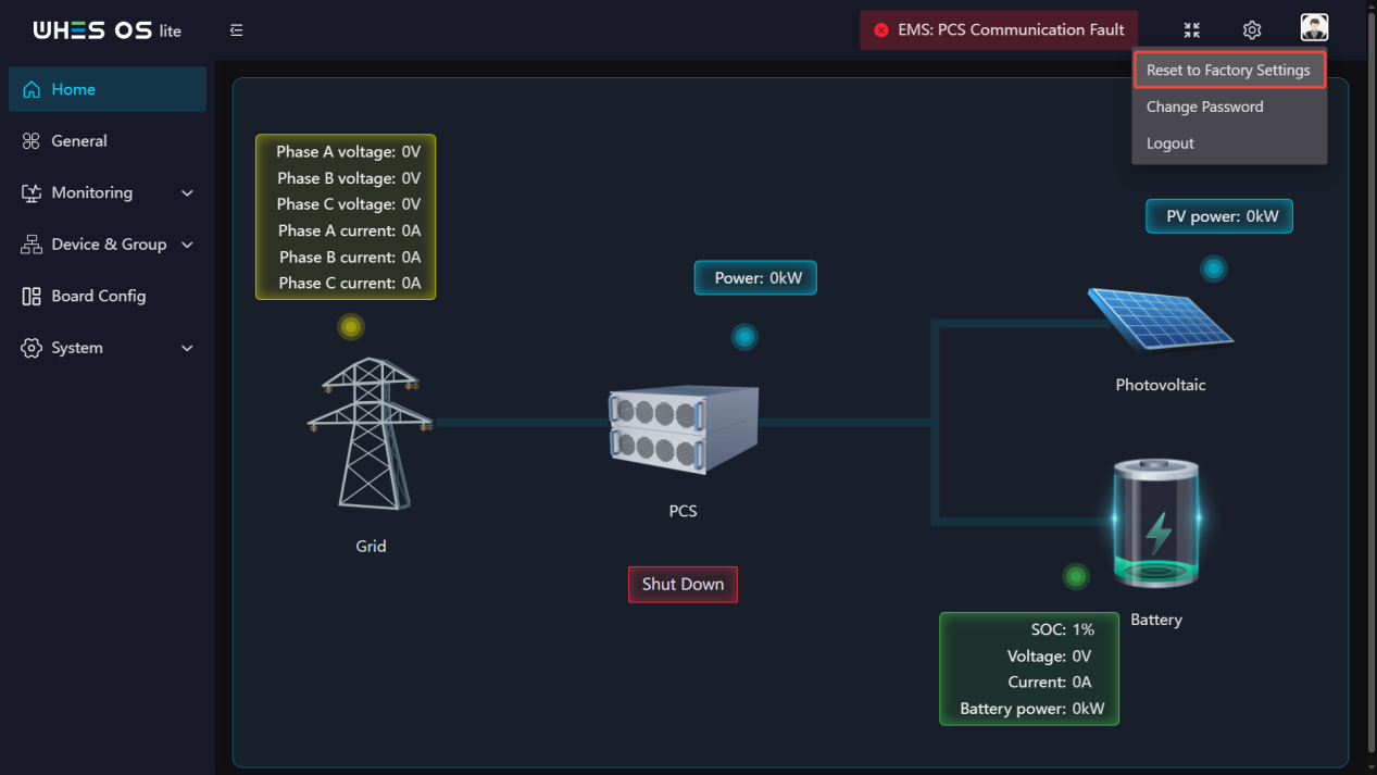
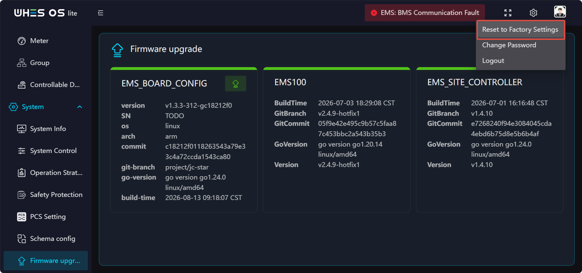
- Click the avatar in the upper right corner, then click the “Reset to Factory Settings” option that appears.
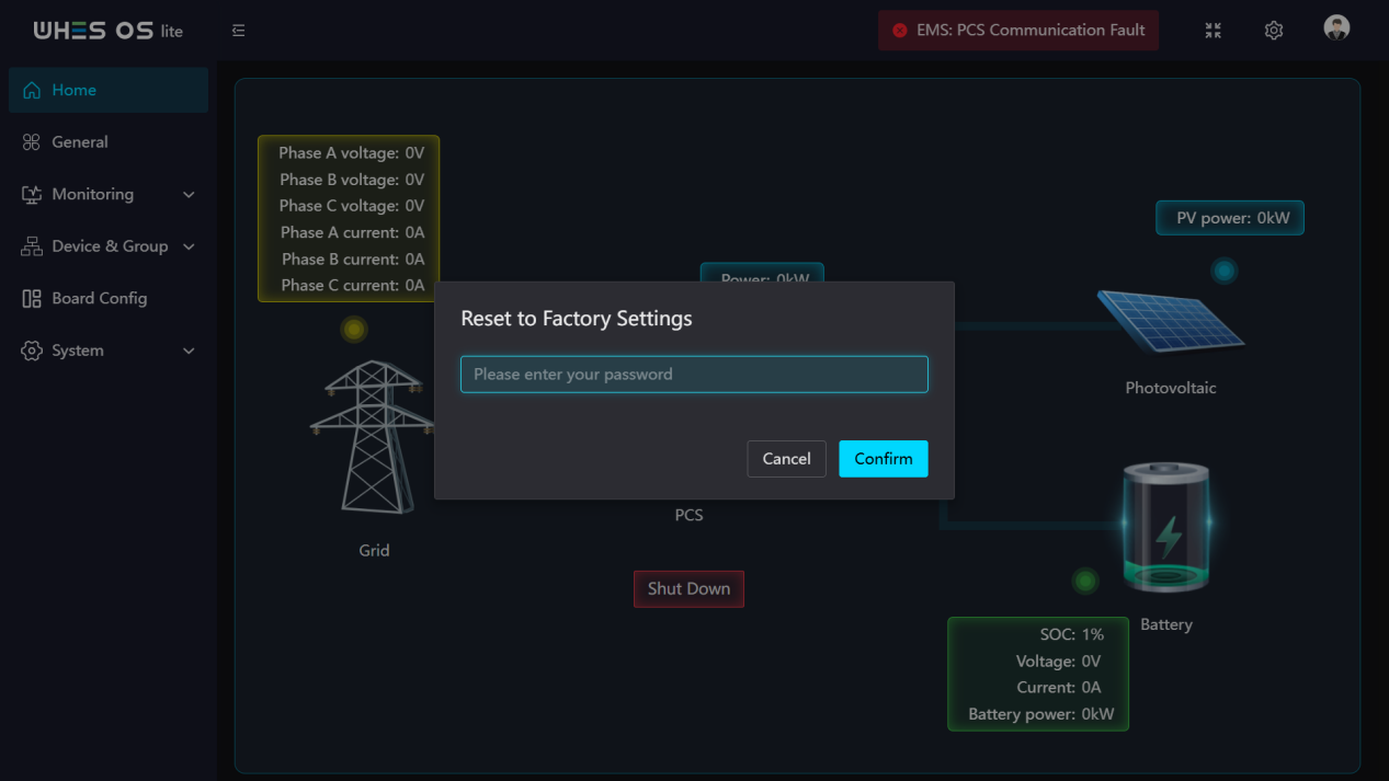
- Please enter your password correctly; after confirmation, the device will be restored to factory settings.
- After completing the operation, all settings will be restored to their default state. The device will perform the following data processing operations:
(1) Collected personal information: All personally identifiable information collected and locally stored on the device shall be permanently deleted; this deletion is irreversible.
(2) Operational business data: All operational business data related to power station operations—including charge/discharge history records, alarm logs, statistical reports, event records, etc.—shall be permanently deleted; this deletion is irreversible.
(3) User‑defined parameters: All user‑configured parameters—including site information, charge/discharge policies, communication configurations, alarm thresholds, networking parameters, etc.—shall be permanently deleted and restored to factory‑default settings.
(4) User passwords: All login passwords configured by the user shall be permanently deleted; the system will be reverted to its factory‑default login password.
(5) Keys and digital signatures: All business keys, communication keys, and custom digital signature information imported or generated by the user shall be permanently deleted; however, the root key and the factory‑preconfigured digital signature built into the device will remain intact and not be deleted.
The password you previously set will be reset to the default initial password. The operating steps are as follows:
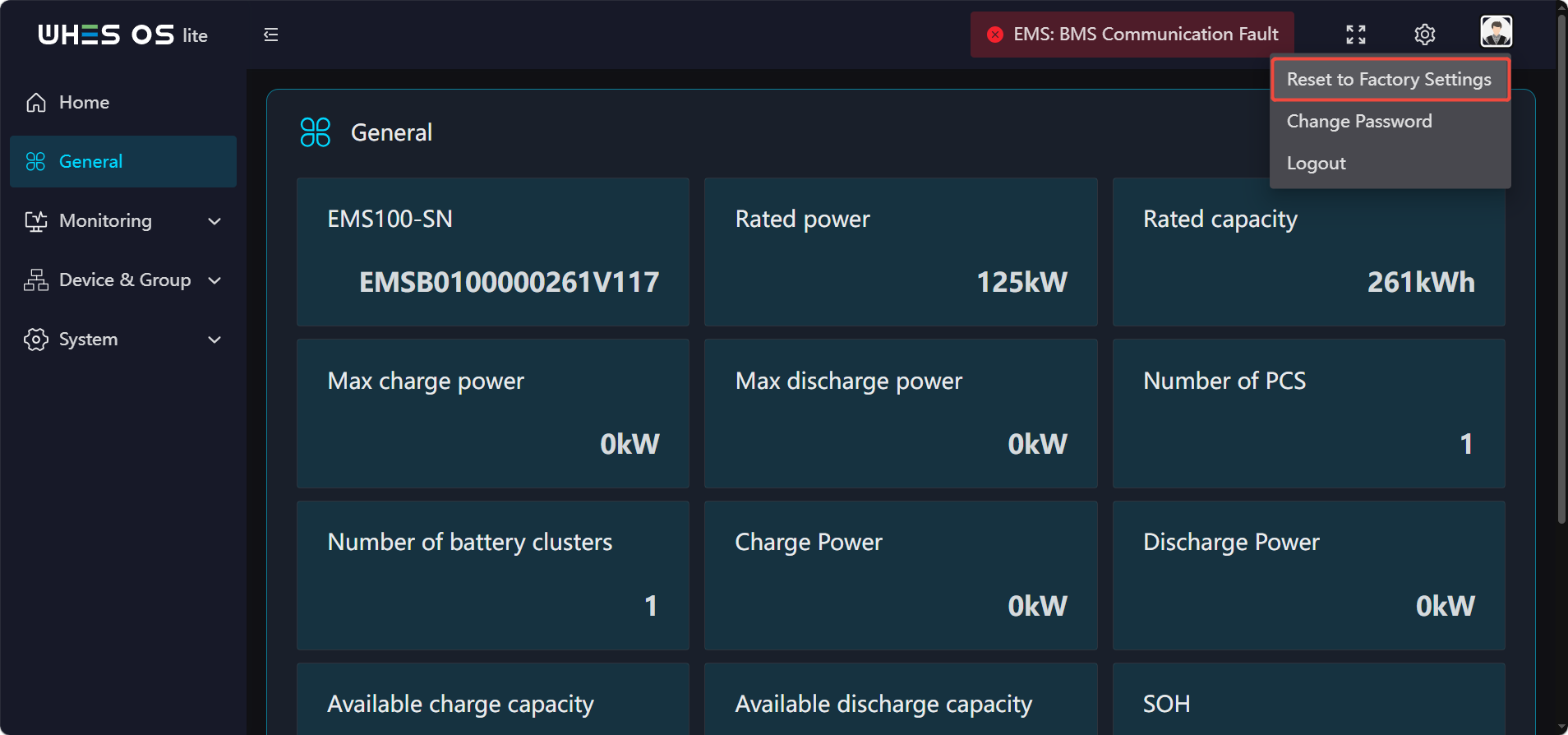
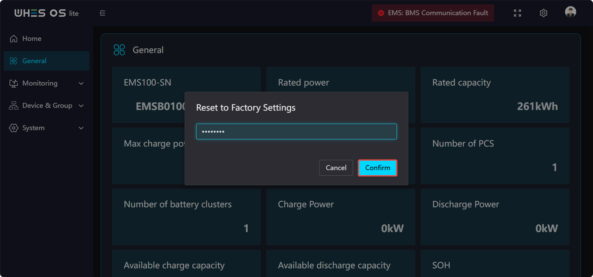
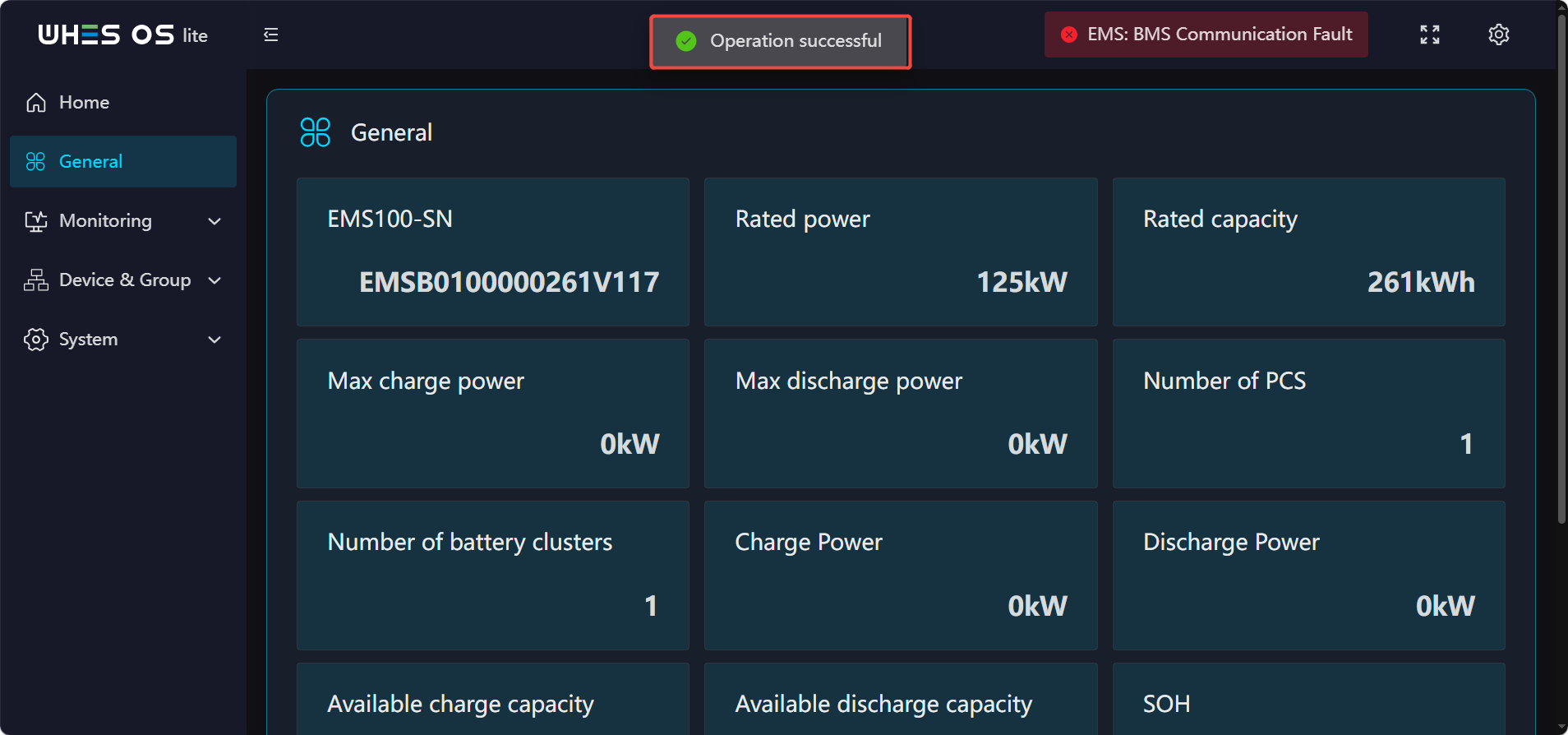
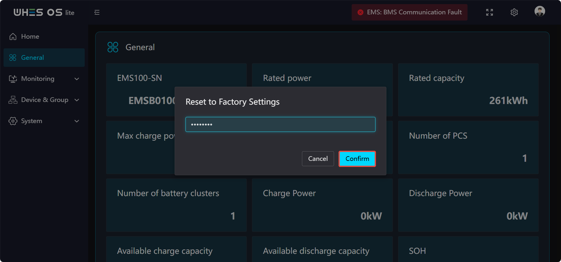
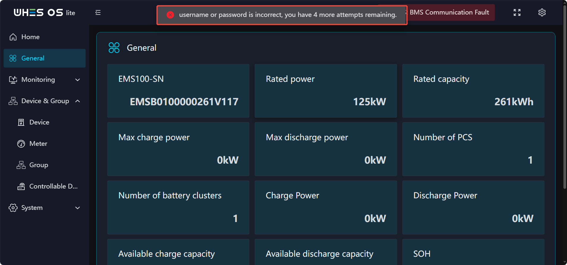
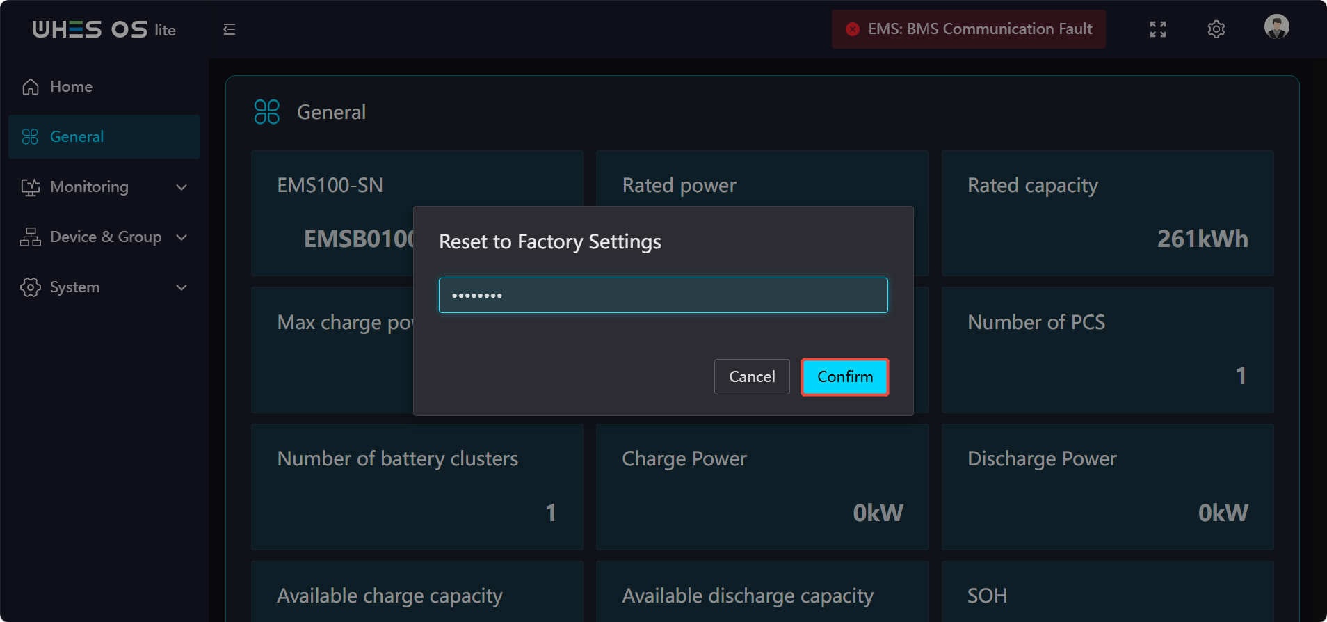
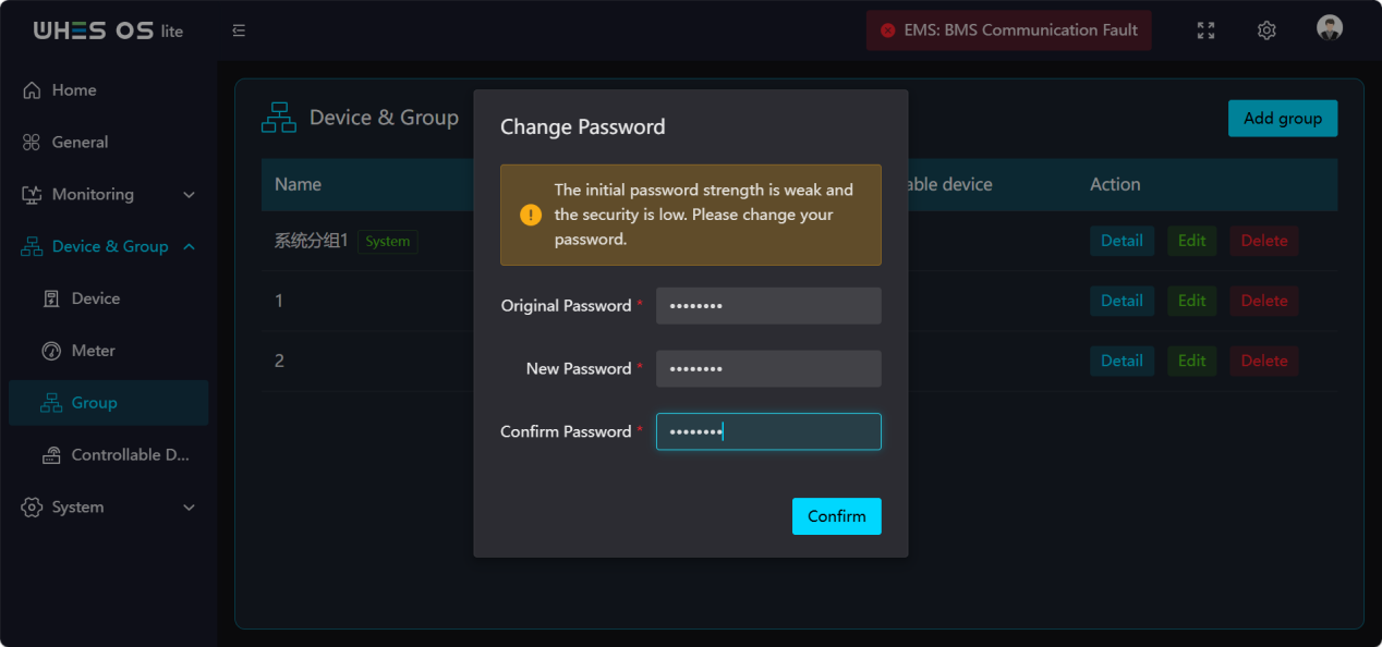
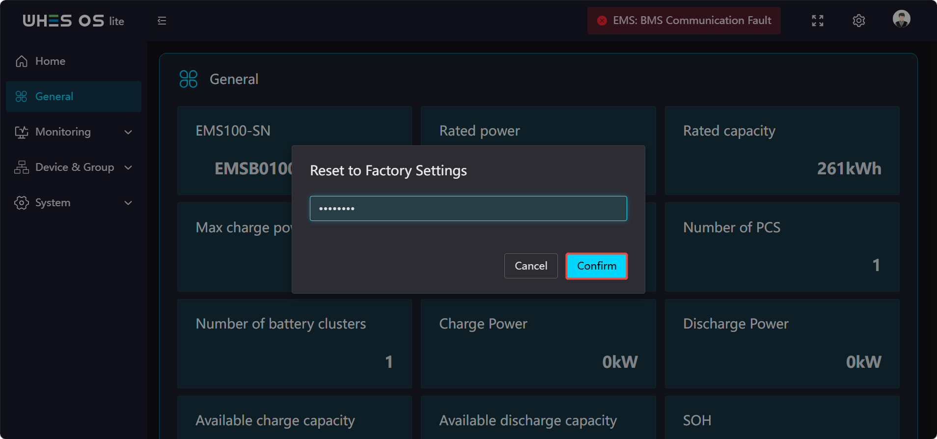
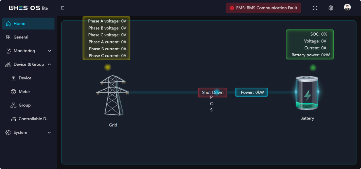
- Tap your profile picture, select [Reset to Factory Settings] from the pop‑up window, and enter your original password to complete the reset;
- After the reset is completed, attempt to log in using your previous password; you will be prompted that the password is incorrect. Once the device has been reset, its password has been restored to the default initial password;
- Enter the default initial password to log in; the system will then automatically display an option to change the password;
- Set a new password, save it, and use this new password to log in normally.
The Firmware upgrade version will not revert after performing a factory reset.
The operating steps are as follows:
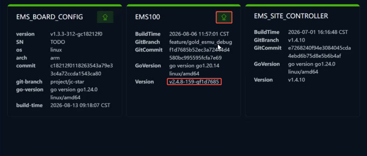
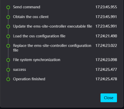
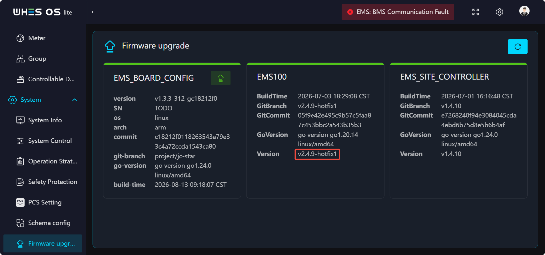
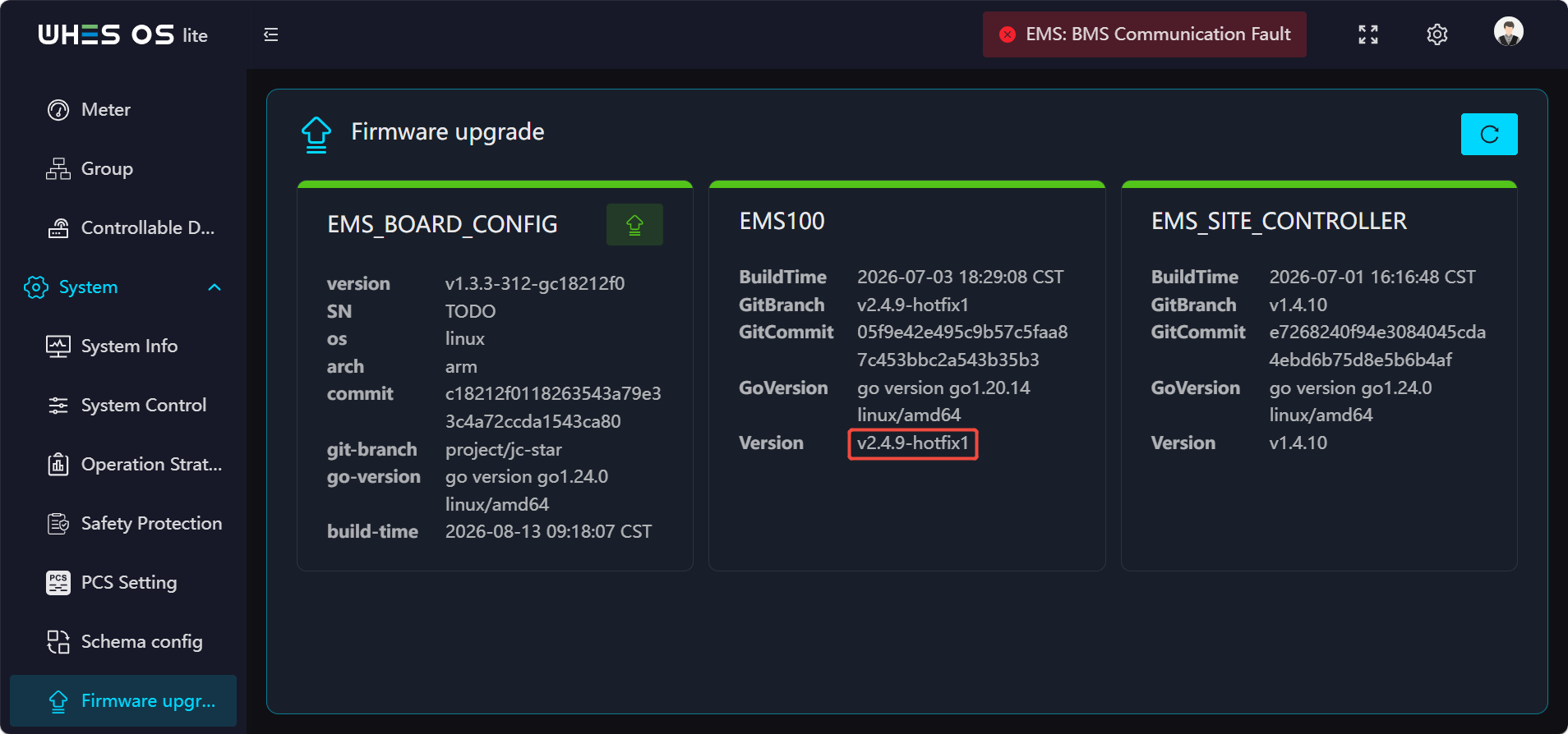
- First, check the device’s current version.
- Click the Update button and wait for the upgrade process to complete.
- After the upgrade is finished, verify the device version again.
- Execute the factory reset.
- After the reset is complete, inspect the device and confirm that its version matches the version prior to the reset.
- This section only verifies that after performing a factory reset, the updated firmware version will not revert; for detailed instructions on how to upgrade the firmware, please refer to the “Firmware Upgrade” section in the documentation.
Change Password
Feature Screen:
Functions:
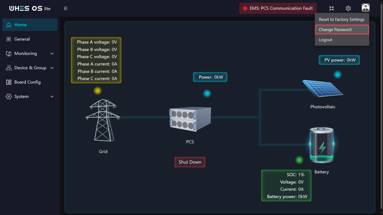
- Click the avatar in the upper right corner, then click the “Change Password” option that appears.
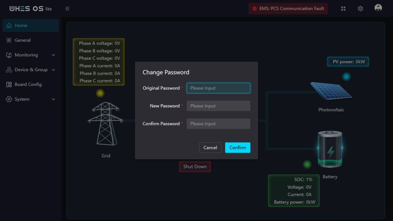
- Enter the original password correctly.
- Enter your new password twice, then click “Confirm” – Password changed successfully.
Logout
Feature Screen:
Functions:
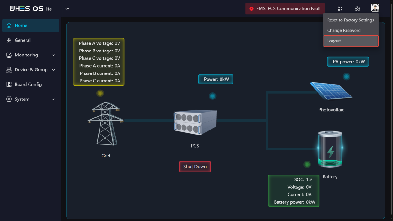
- Click the avatar in the upper right corner, then click the “Logout” option that appears.
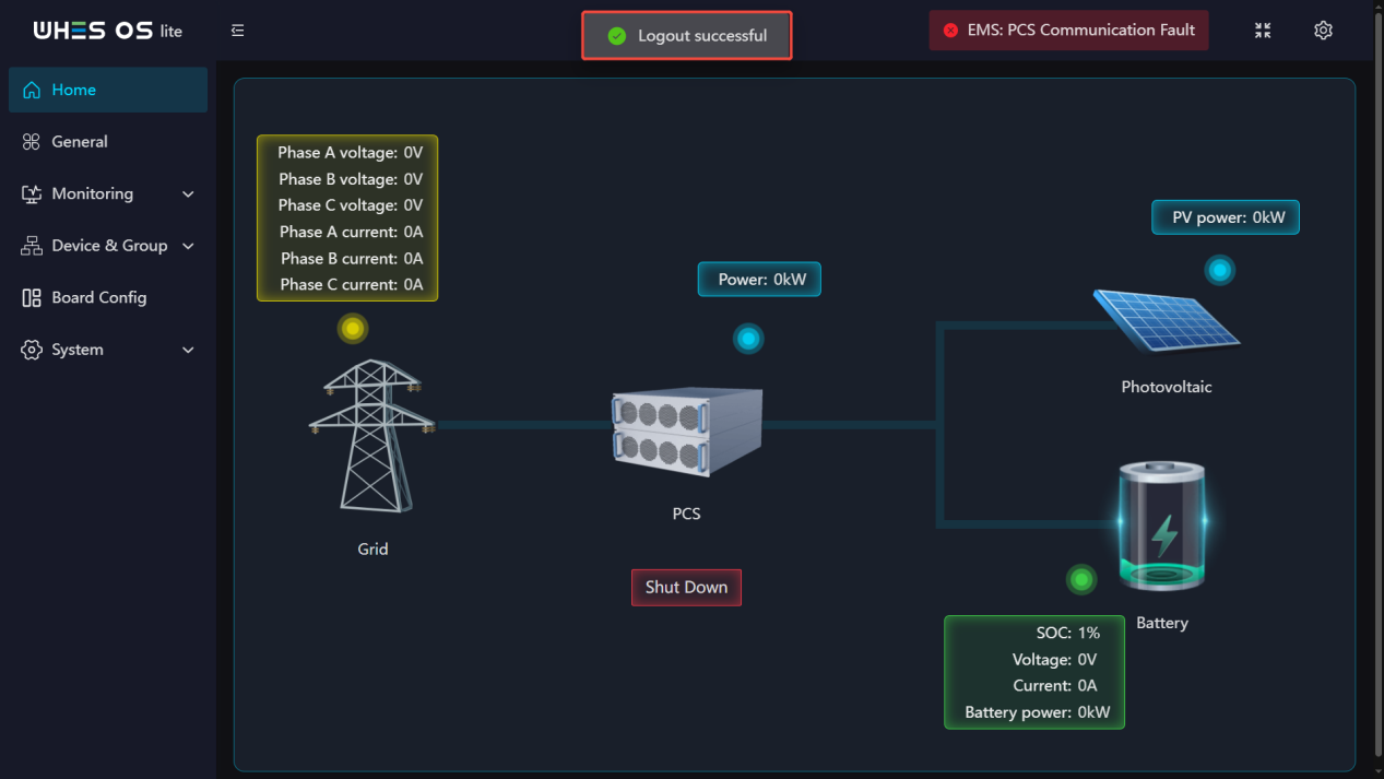
- The system will prompt you that you have been successfully logged out.
Home
Feature Screen:
Functions:
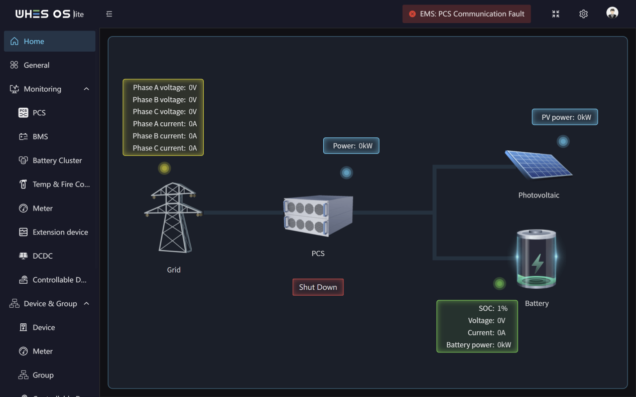
- This page shows the energy flow trends in the power plant and the real‑time operational status of the PCS, the Battery, the Grid and the Photovoltaic. The system operational status and data are refreshed every 5 seconds.
- The flow shows the data of the three‑phase voltage and current of the grid, the PCS power, the Photovoltaic power as well as the SOC, Voltage, Current, power of the Battery.
- PCS operating status:
- Charging: Indicates that the system is being charged.
- Discharging: Indicates that the system is being discharged.
- Offline: Indicates that the system is offline.
- Standby: Indicates that the device is operating normally, no fault, no charging and discharging is taking place.
- Stop: Indicates that the device has stopped operating.
General
Feature Screen:
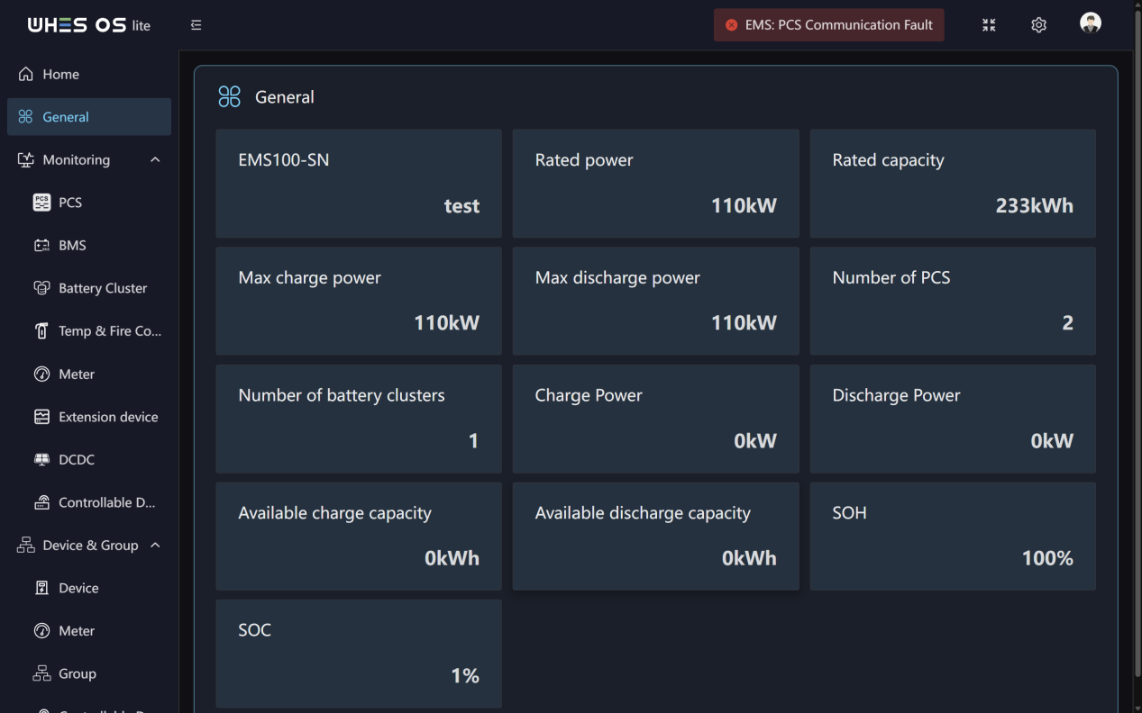
Functions:
This page shows the basic general information of the system. There are EMS‑SN, Rated power, Rated capacity, Max charge power, Max discharge power, Number of PCS, Number of battery clusters, Charge power, Discharge power, Available charge capacity, Available discharge capacity, SOH and SOC.
Monitoring
PCS
Feature Screen:

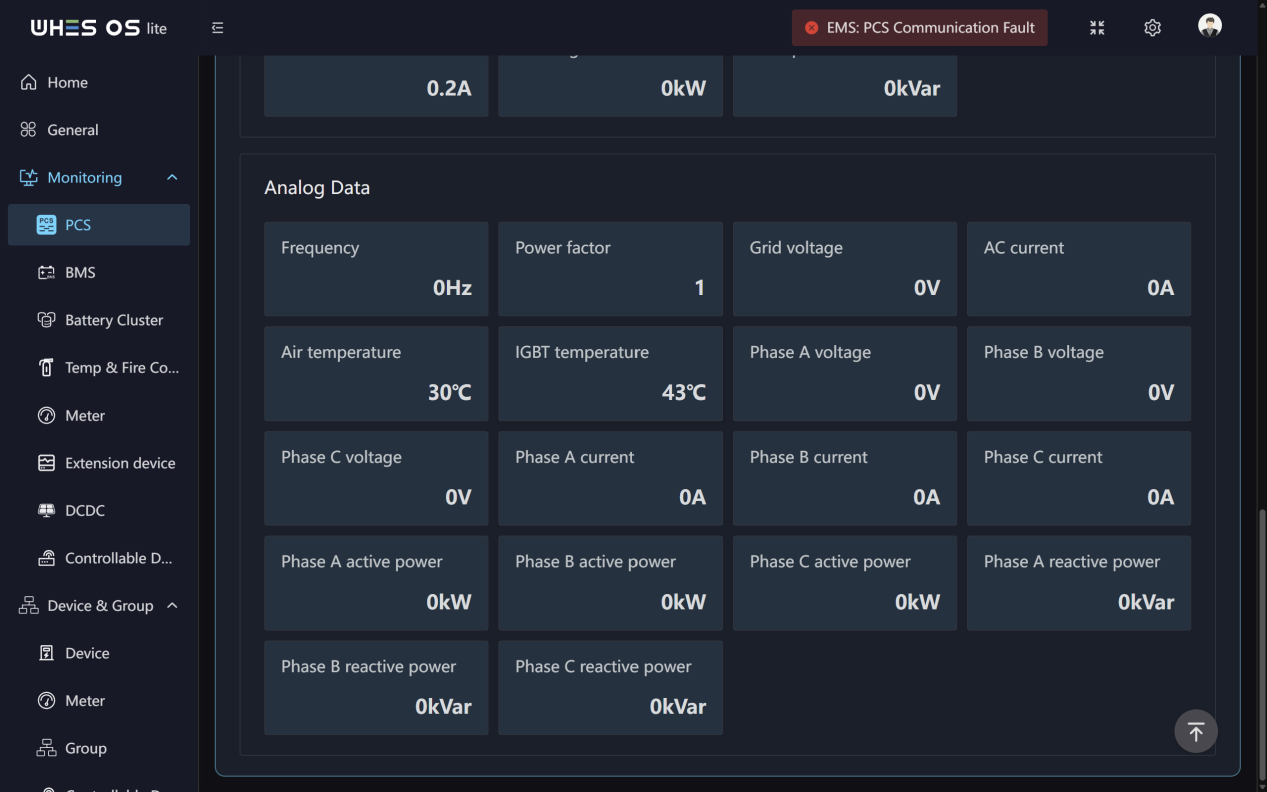
Functions:
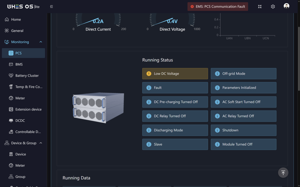
- Real‑time monitoring of DC Current, DC Voltage and three‑phase Voltage data.
- You can monitor PCS all running status.
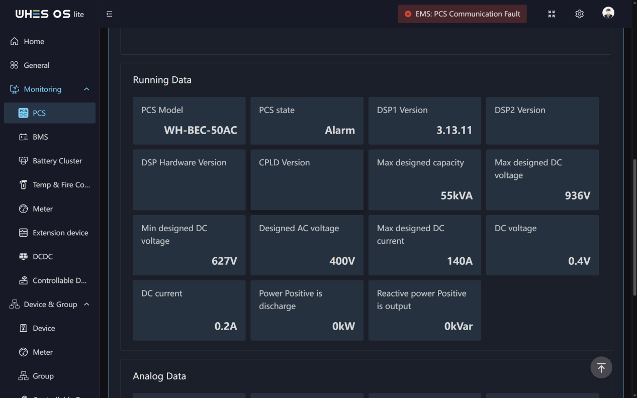
- Display PCS running data and analog data, including design capacity, design max and min designed voltage, frequency, power factor, active power and reactive power, etc.
BMS
Feature Screen:
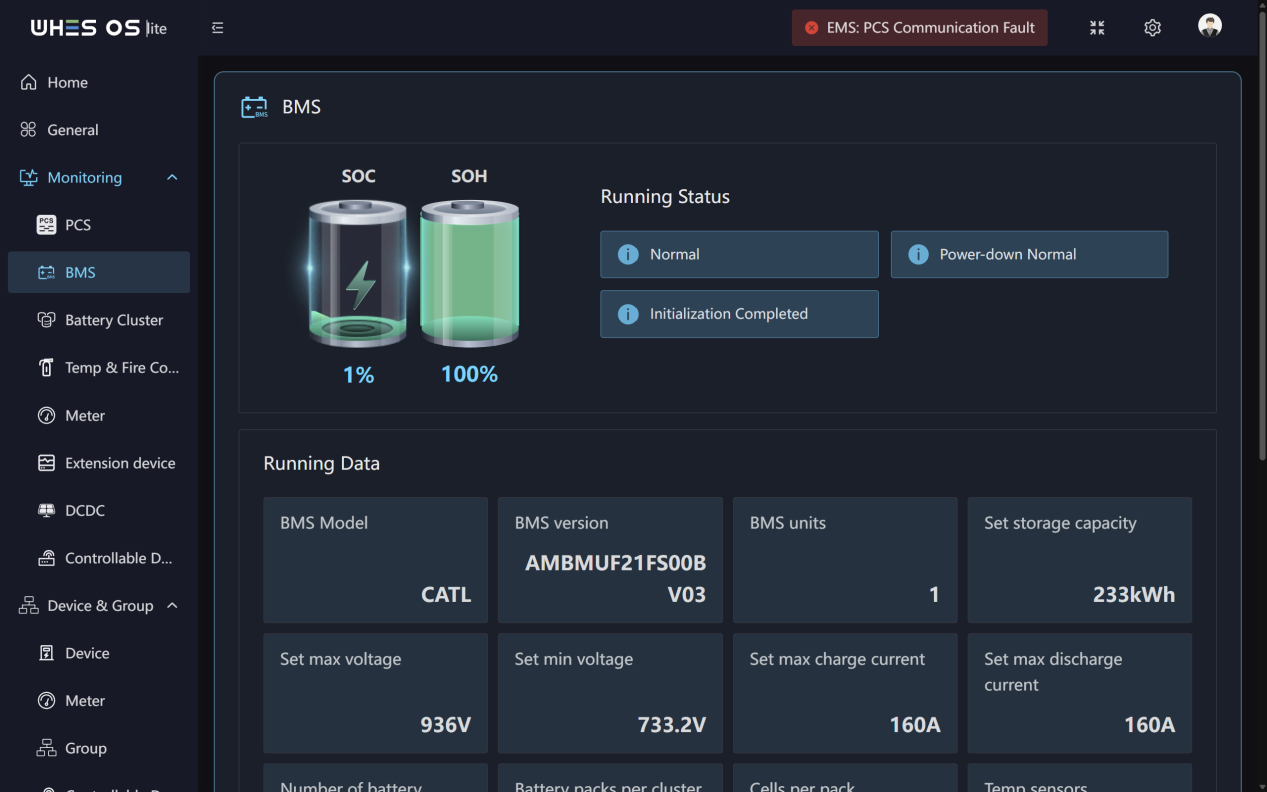
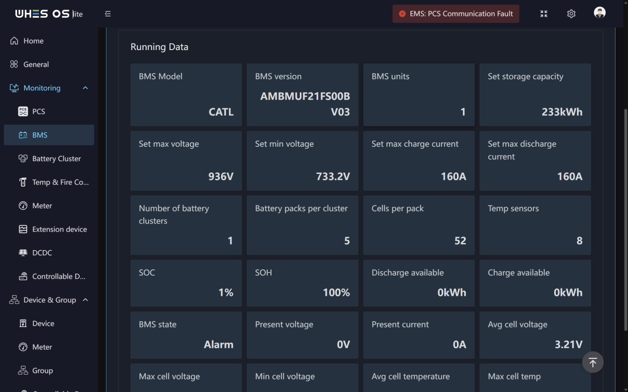
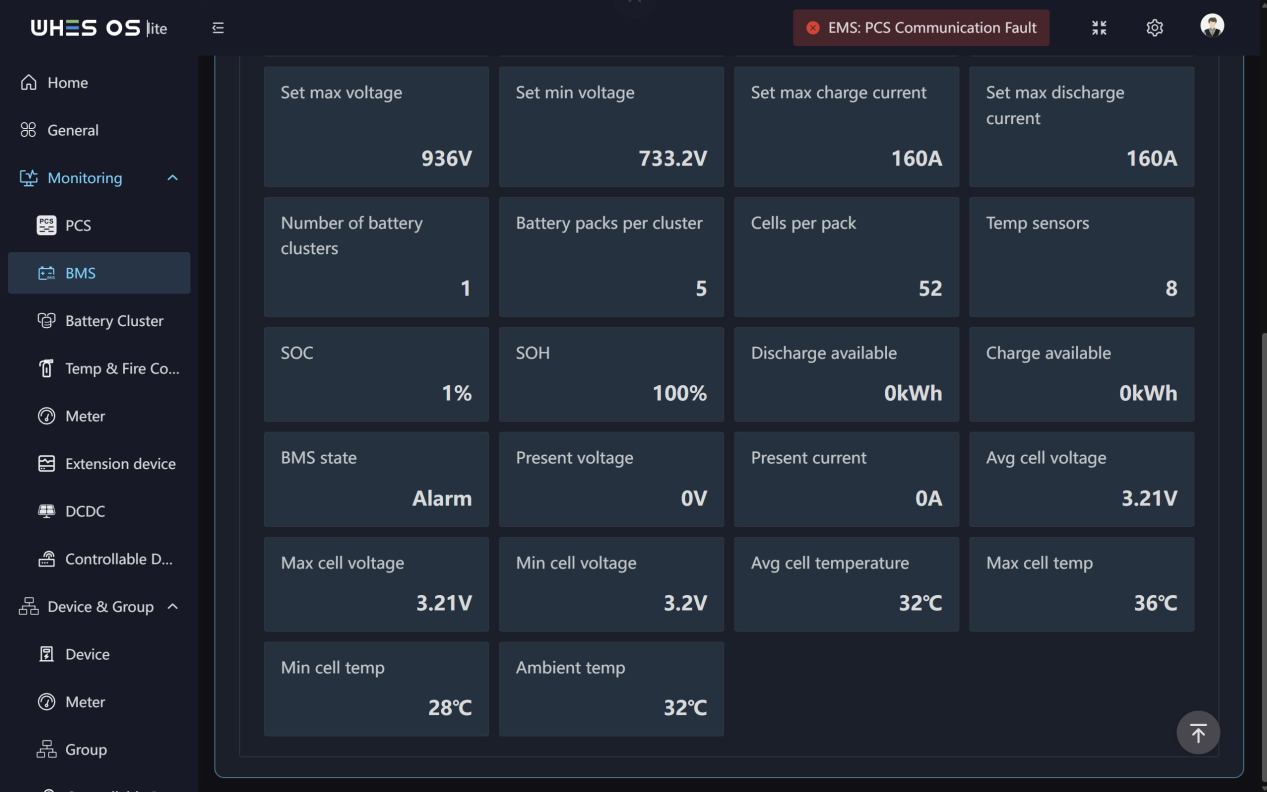
Functions:
- This page displays the monitoring information of SOC/SOH, running status and detailed running data of the battery BMS.
- Also displays the monitoring information of real‑time status and data of all battery clusters.
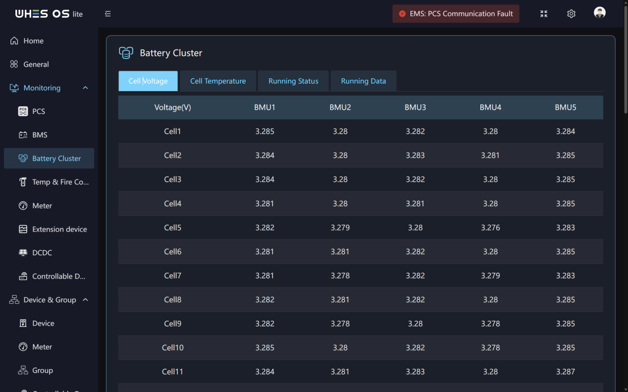
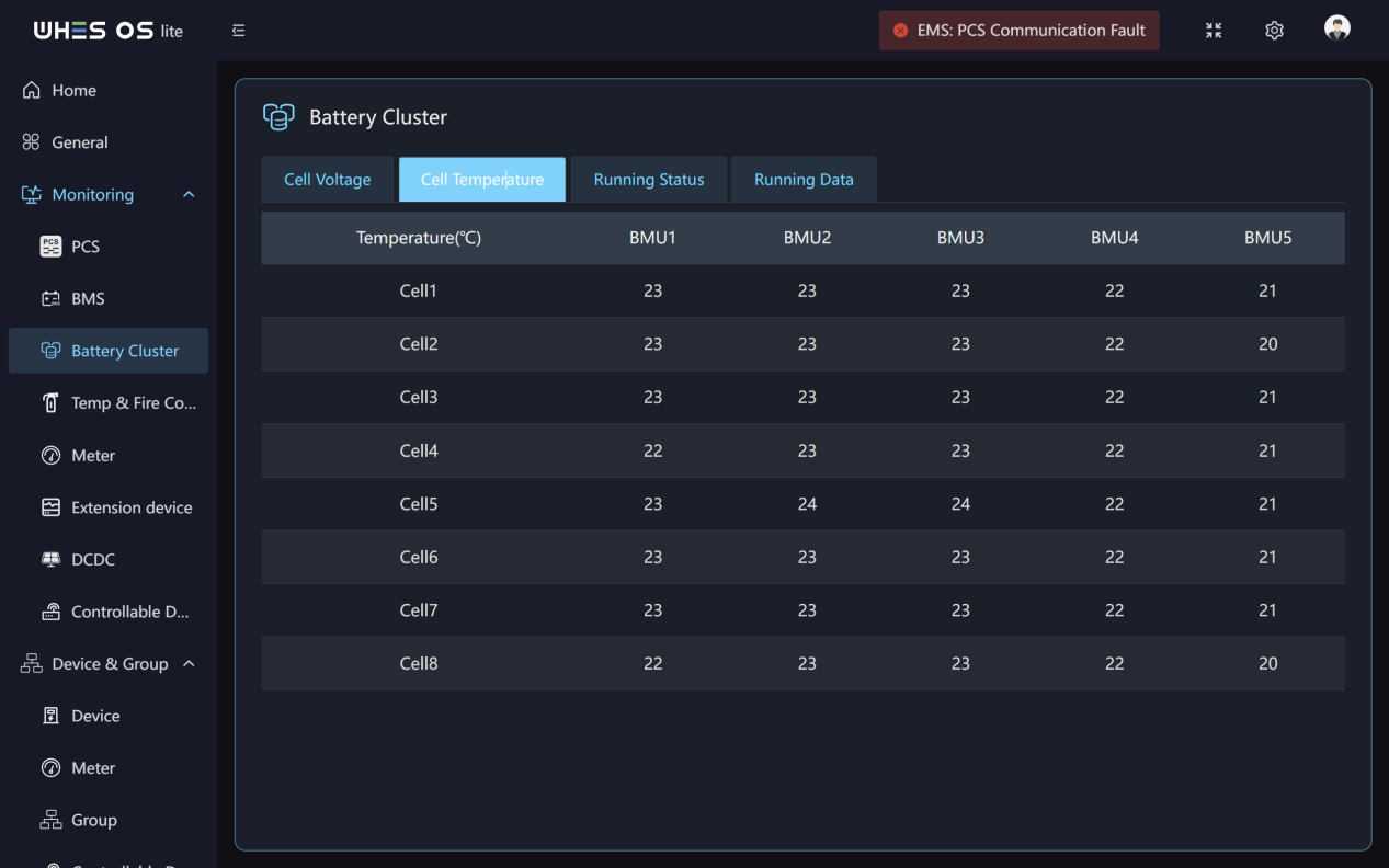
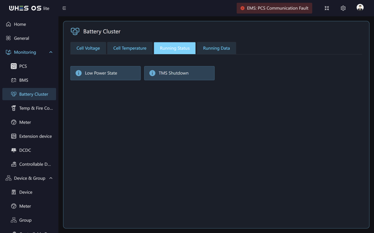
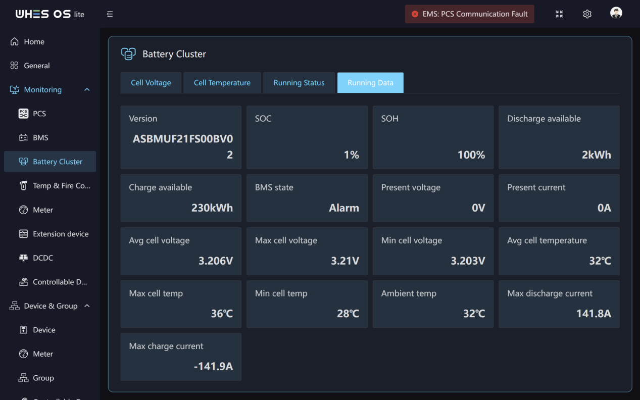
BMS Cluster
Feature Screen:
Functions:
- Monitor the voltage and temperature data for all individual cells in a battery cluster.
- Monitor the running status and running data of all battery clusters.
Temp & Fire Control
Feature Screen:
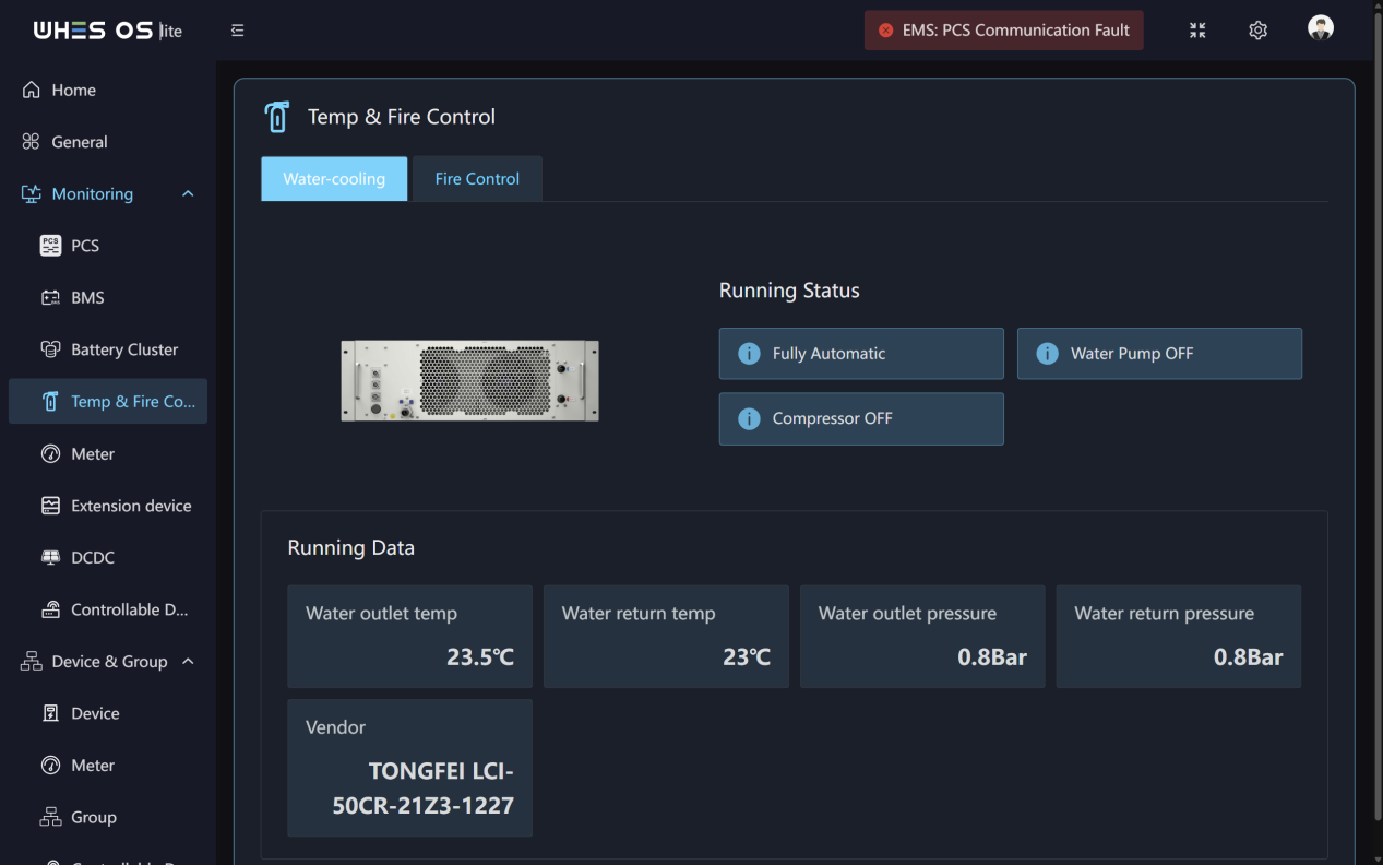
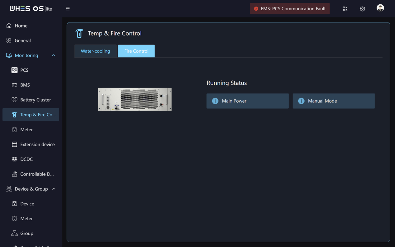
Functions:
- Real‑time monitoring of Water outlet/ return temp, pressure, vendor and running status.
- Real‑time monitoring of all running status of the fire control system.
Meter
Feature Screen:
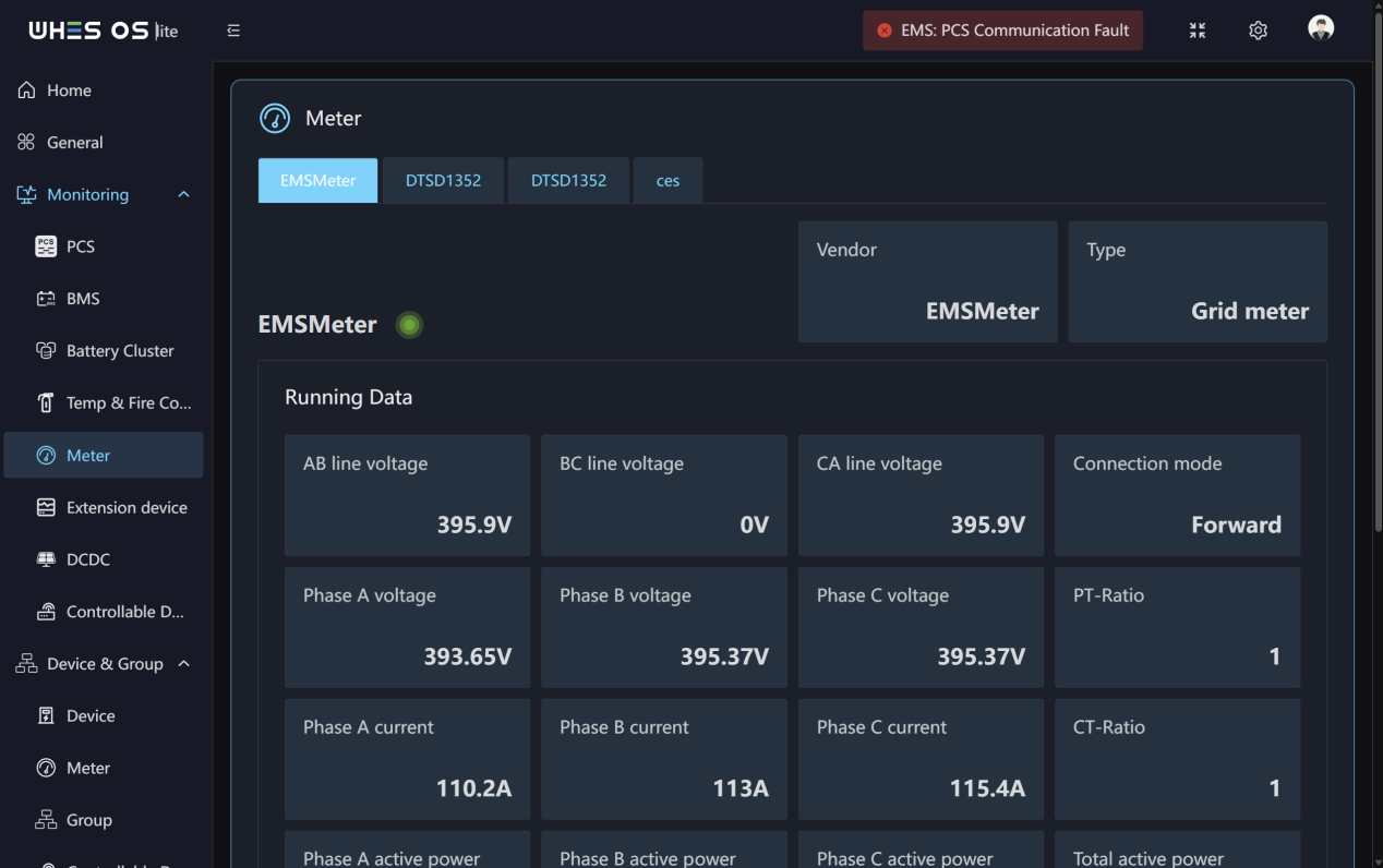
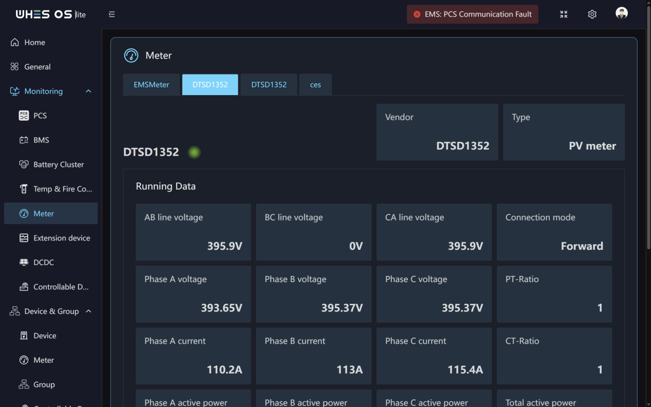
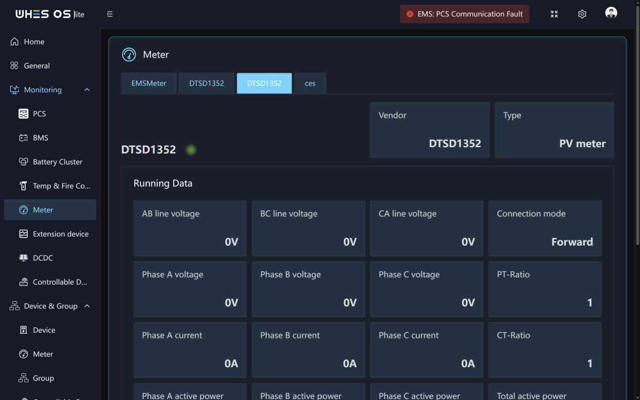
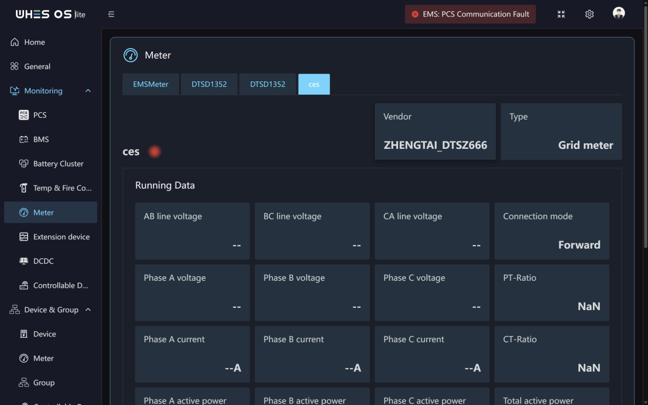
Functions:
- This page shows the vendor and meter type.
- Real‑time monitoring of all running data of all of the meter.
Extension device
Feature Screen:
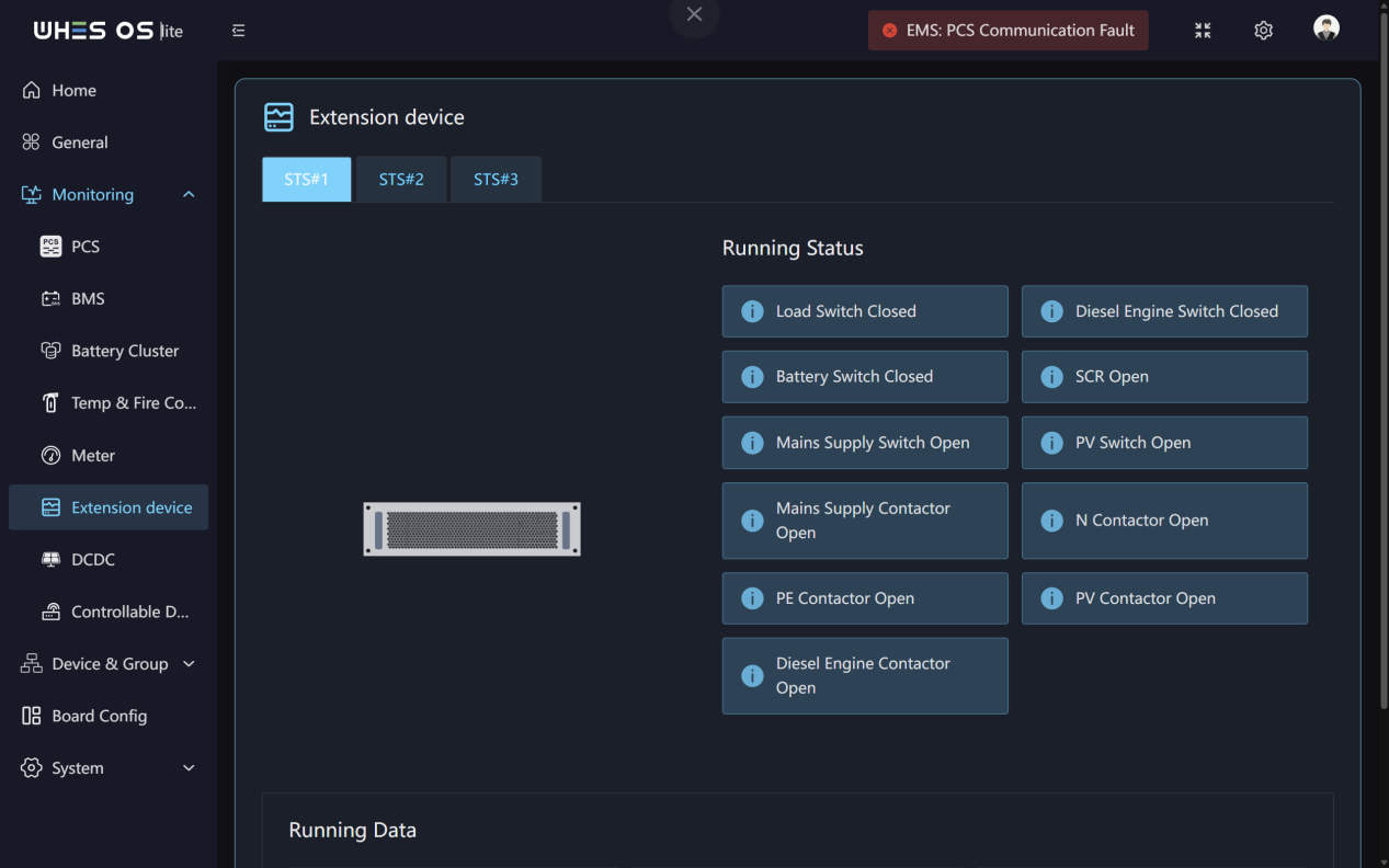
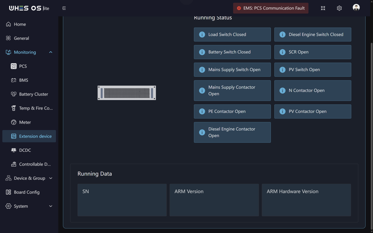
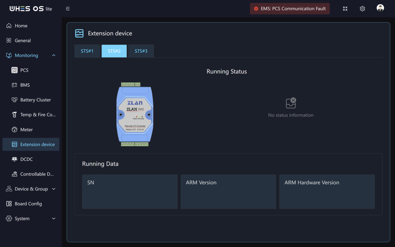
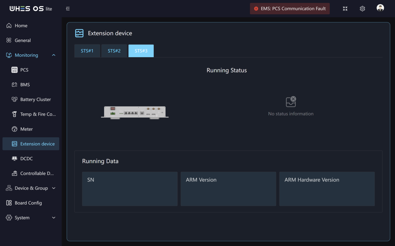
Functions:
Real‑time monitoring of all of the extension device running status and data.
DCDC
Feature Screen:
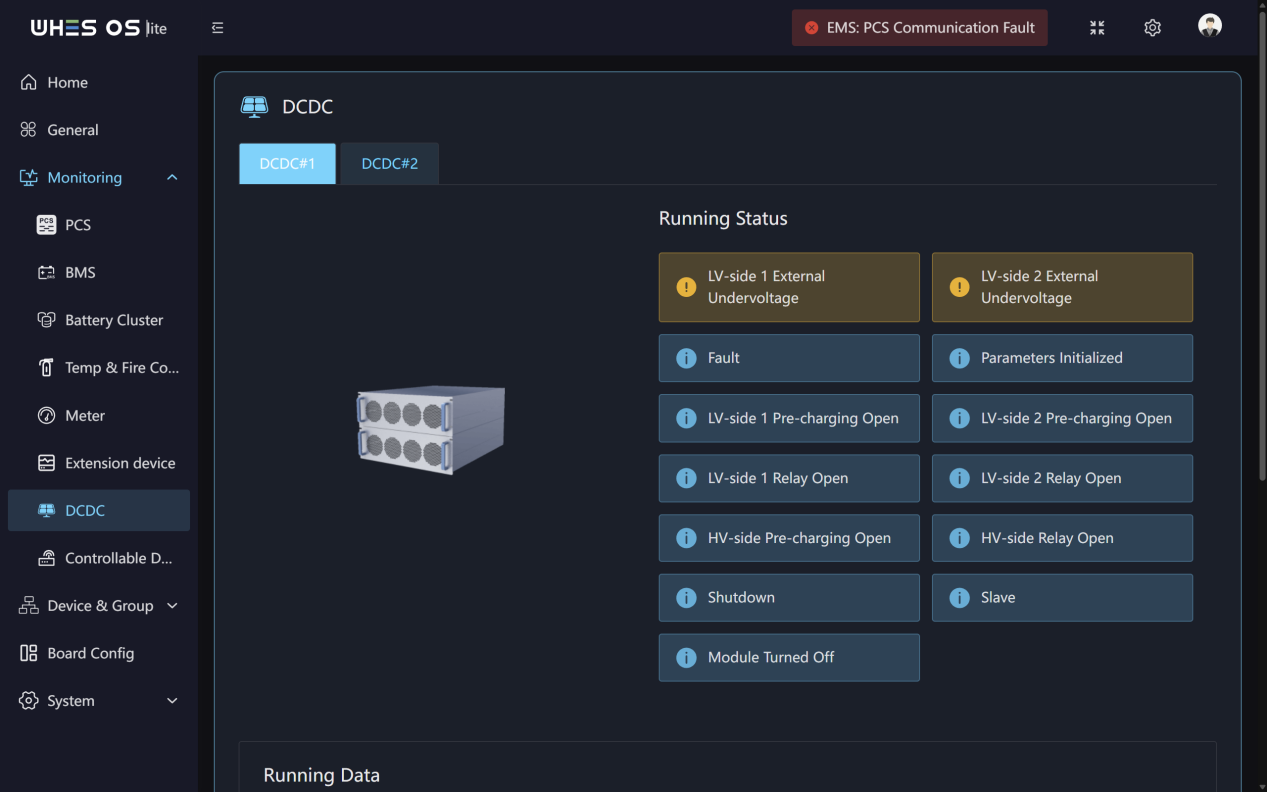
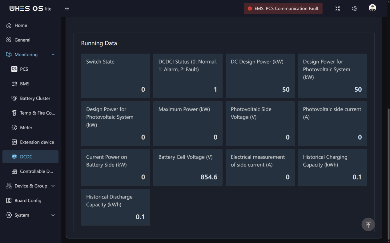
Functions:
Real‑time monitoring of all of the DCDC running status and data.
Controllable Device
Feature Screen:
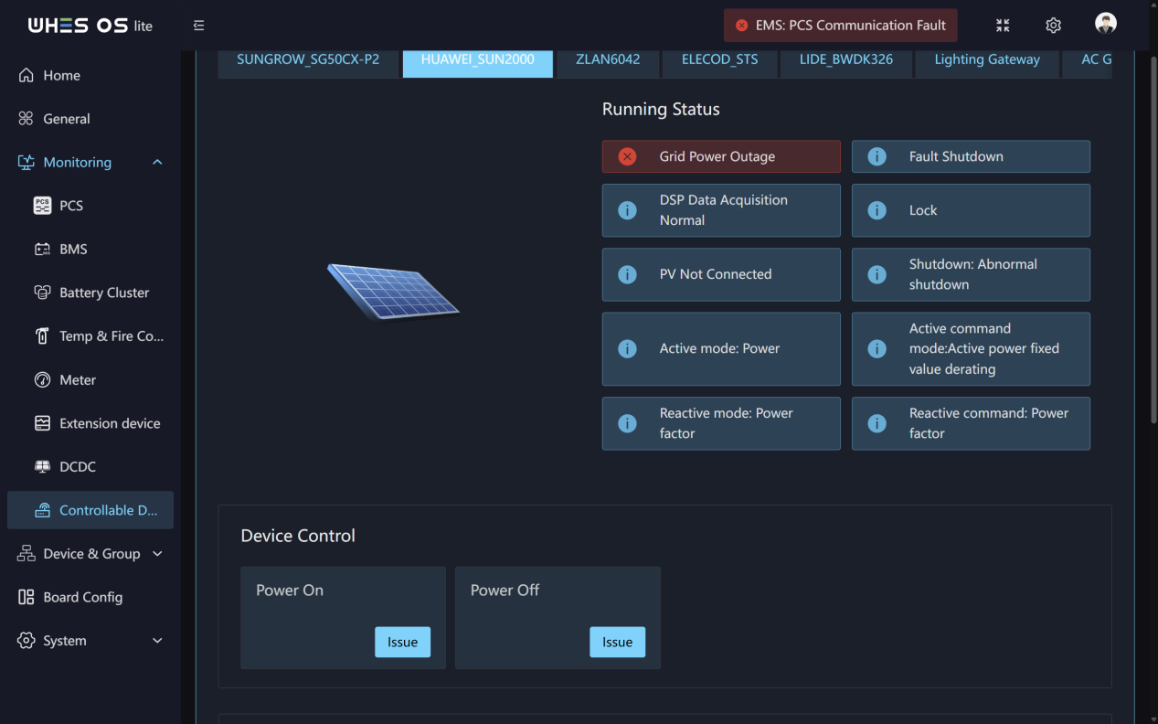
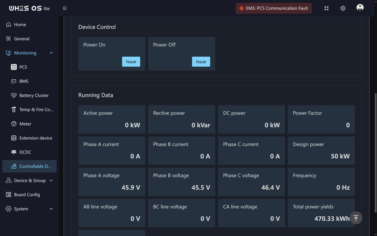
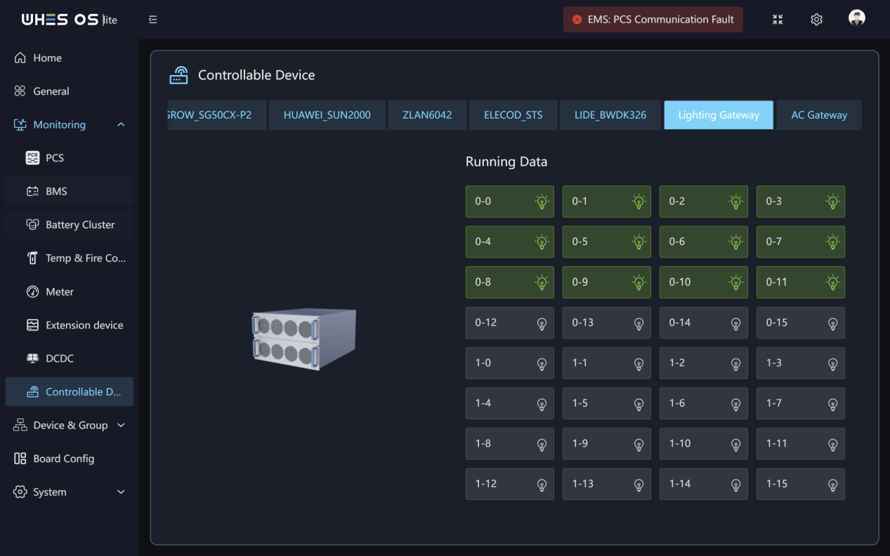
Functions:
- This page monitors all types of controllable devices running data and running status.
- You can turn controllable devices on and off at any time.
Device & Group
Device
Feature Screen:
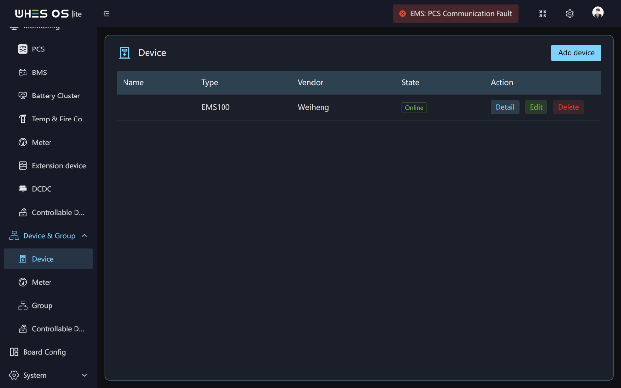
Functions:
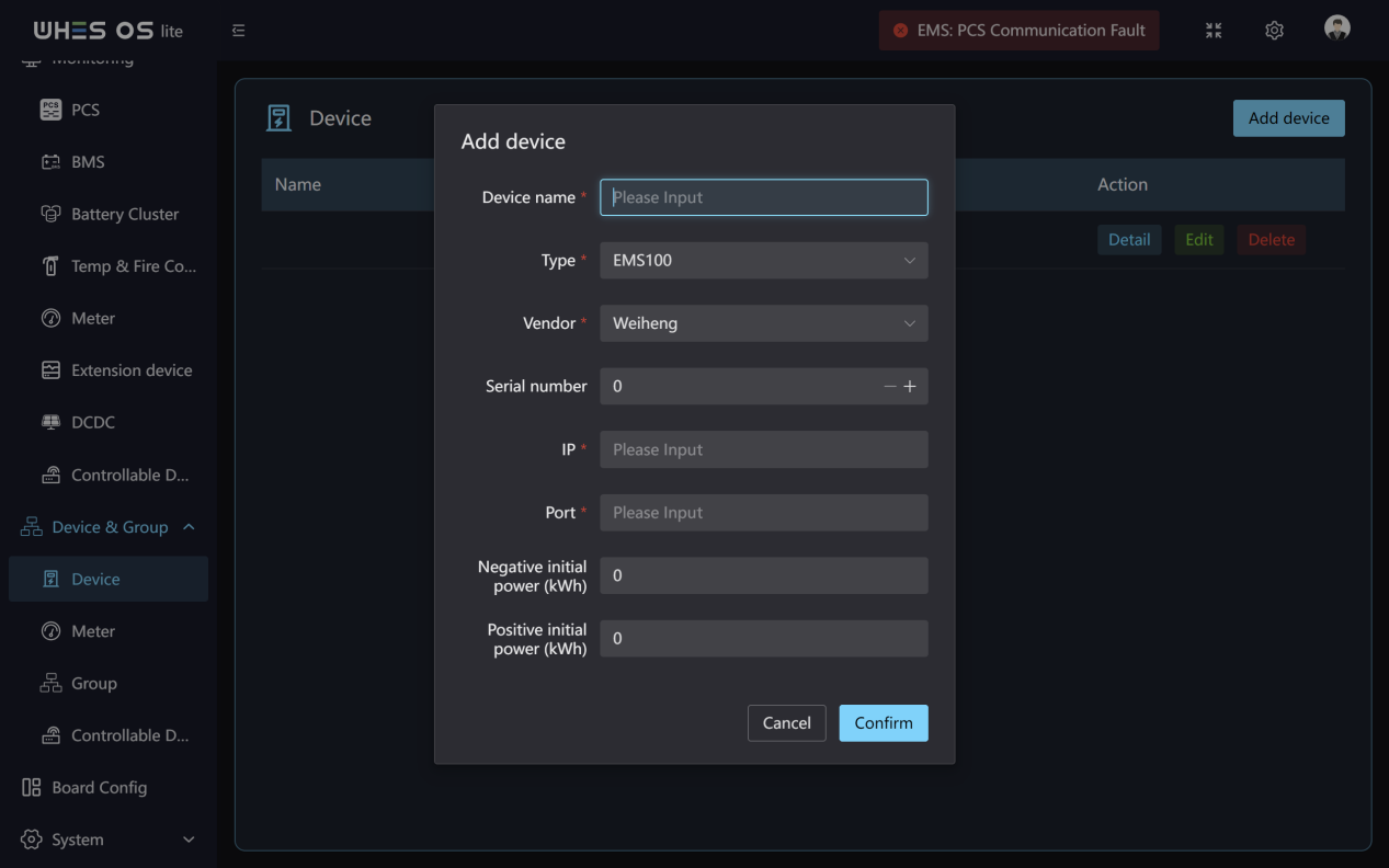
- First click on Add Device button.
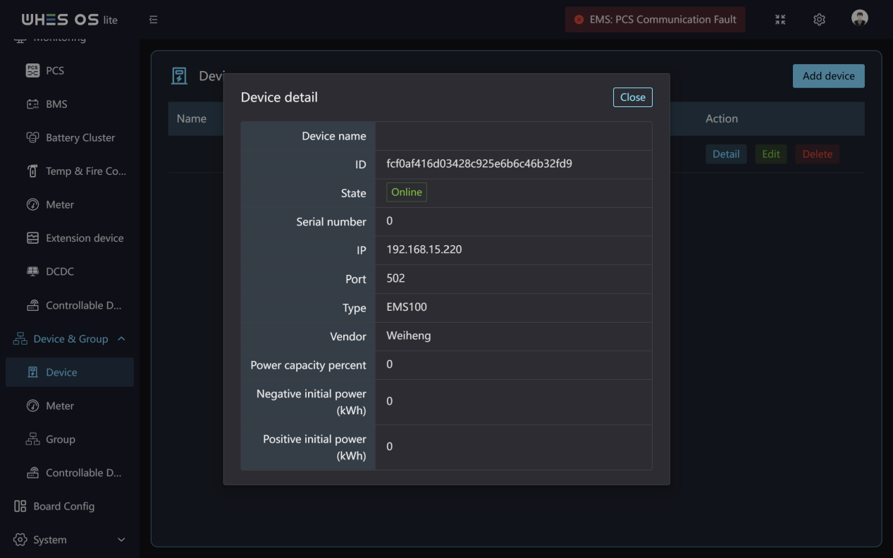
- Complete the following information to finish adding the device: Device name, Device type, Vendor, Serial number, IP, Port, Negative initial power and Positive initial power.
- You can check the device details or edit and delete the device at any time.
Meter
Feature Screen:
Functions:
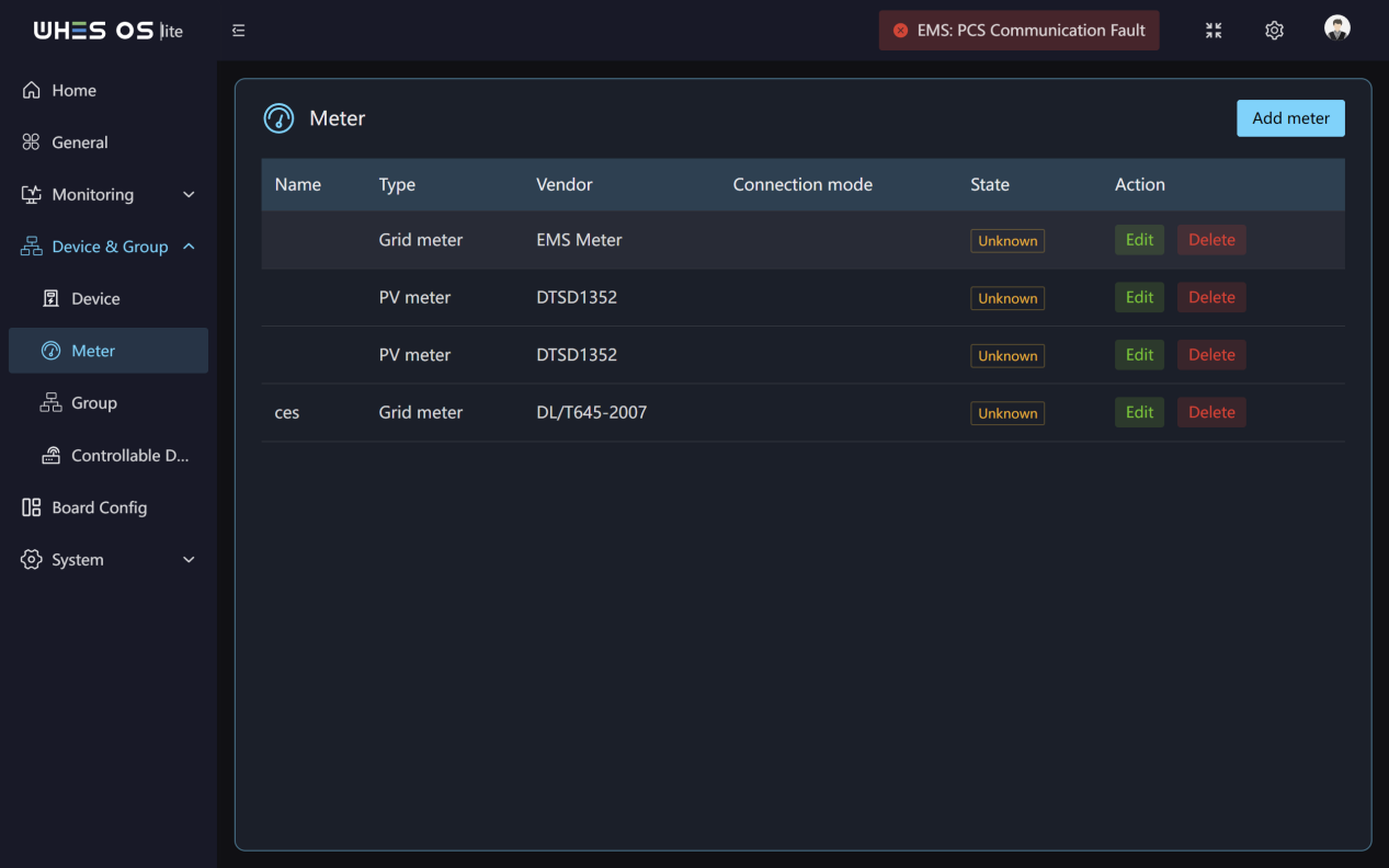
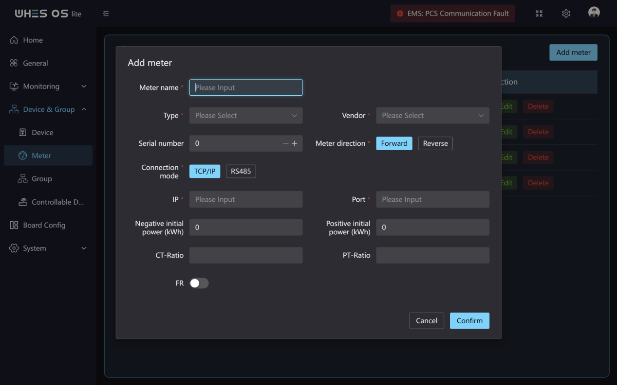
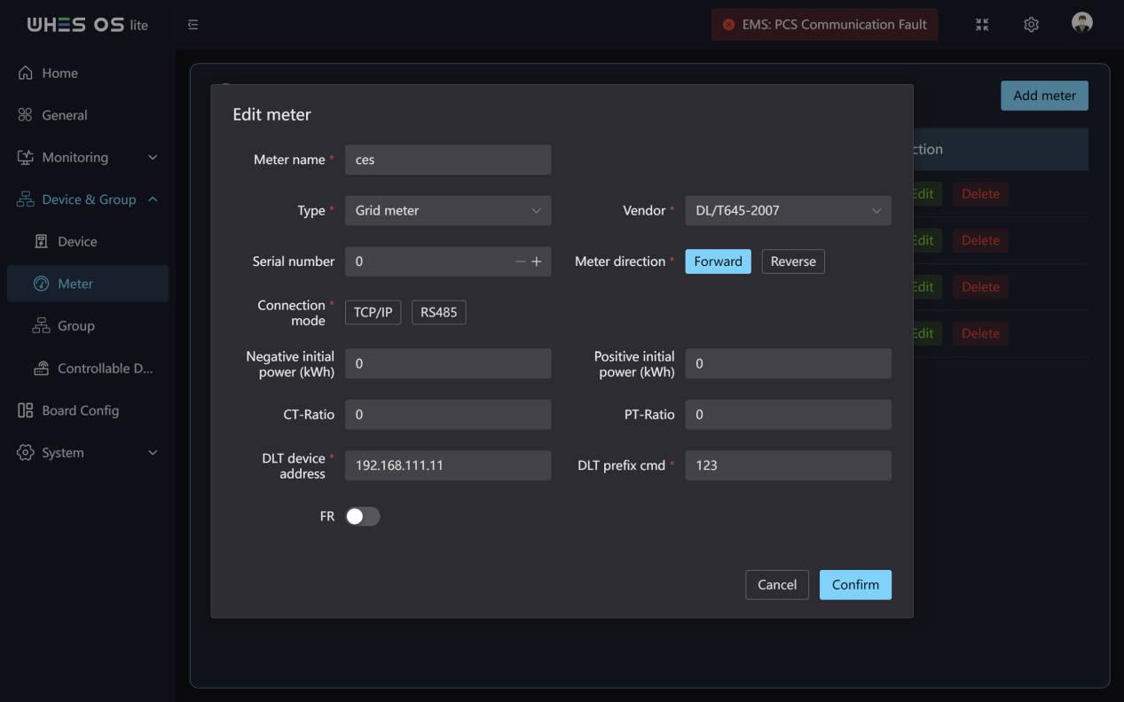
- First click on Add meter button.
- Complete the following information to finish adding the meter: Meter name, Meter type, Vendor, Serial name, Meter direction, IP, Port, Connection mode, Negative initial power and Positive initial power, CT‑Ratio, PT‑Ratio.
- You can check the meter details or edit and delete the meter at any time.
Group
Feature Screen:

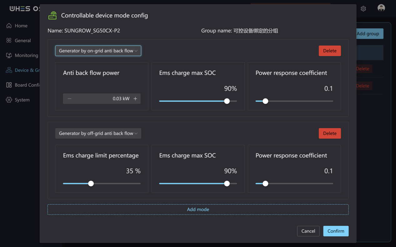
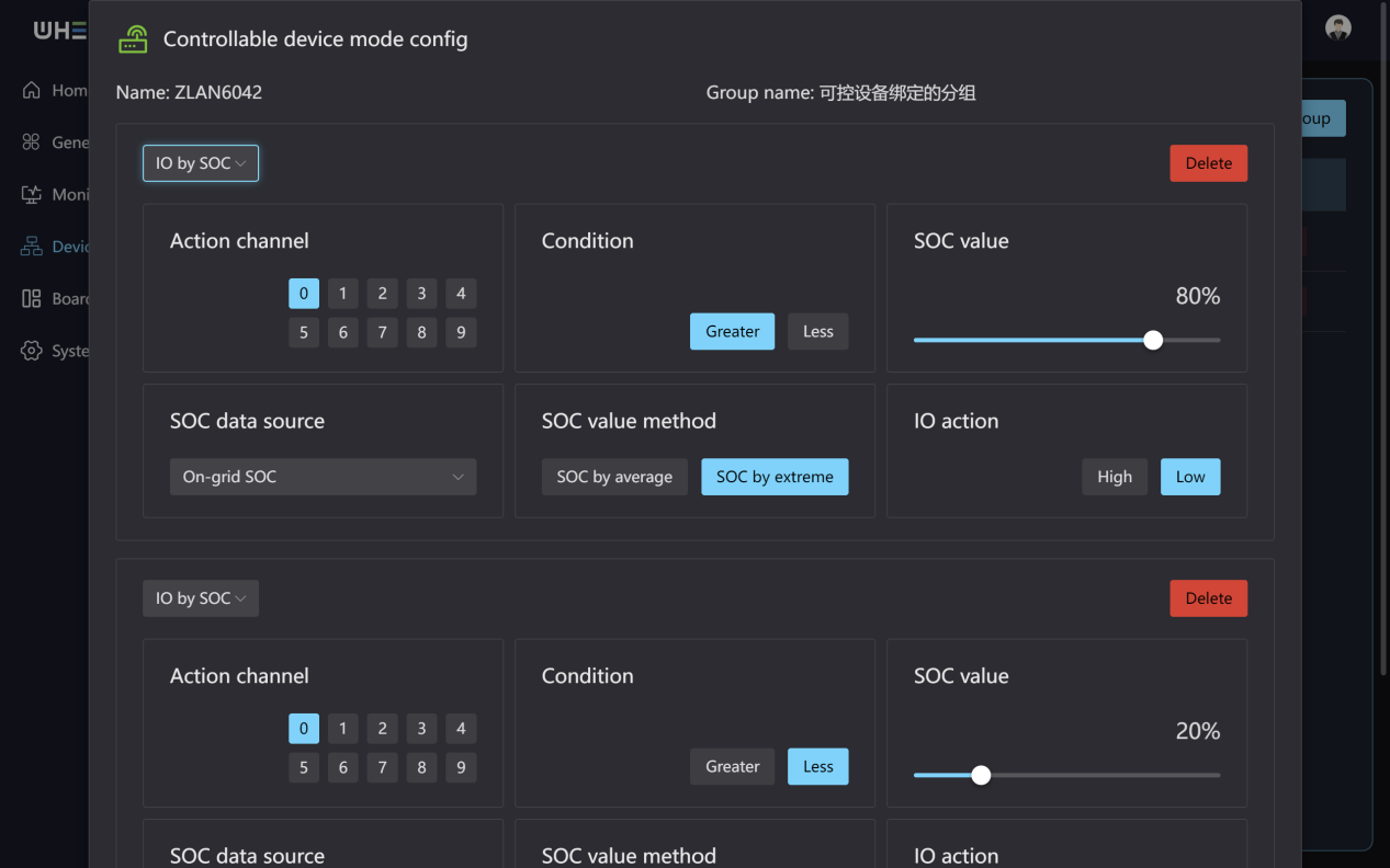
Functions:
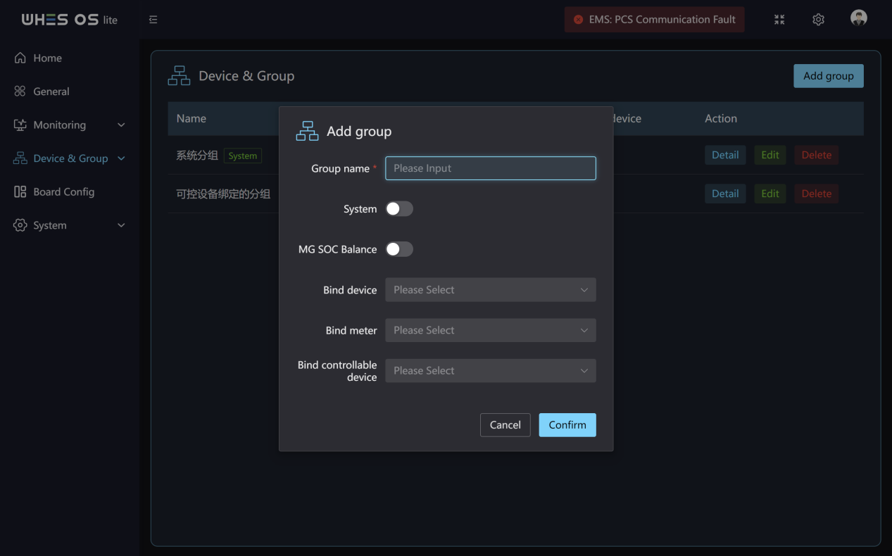
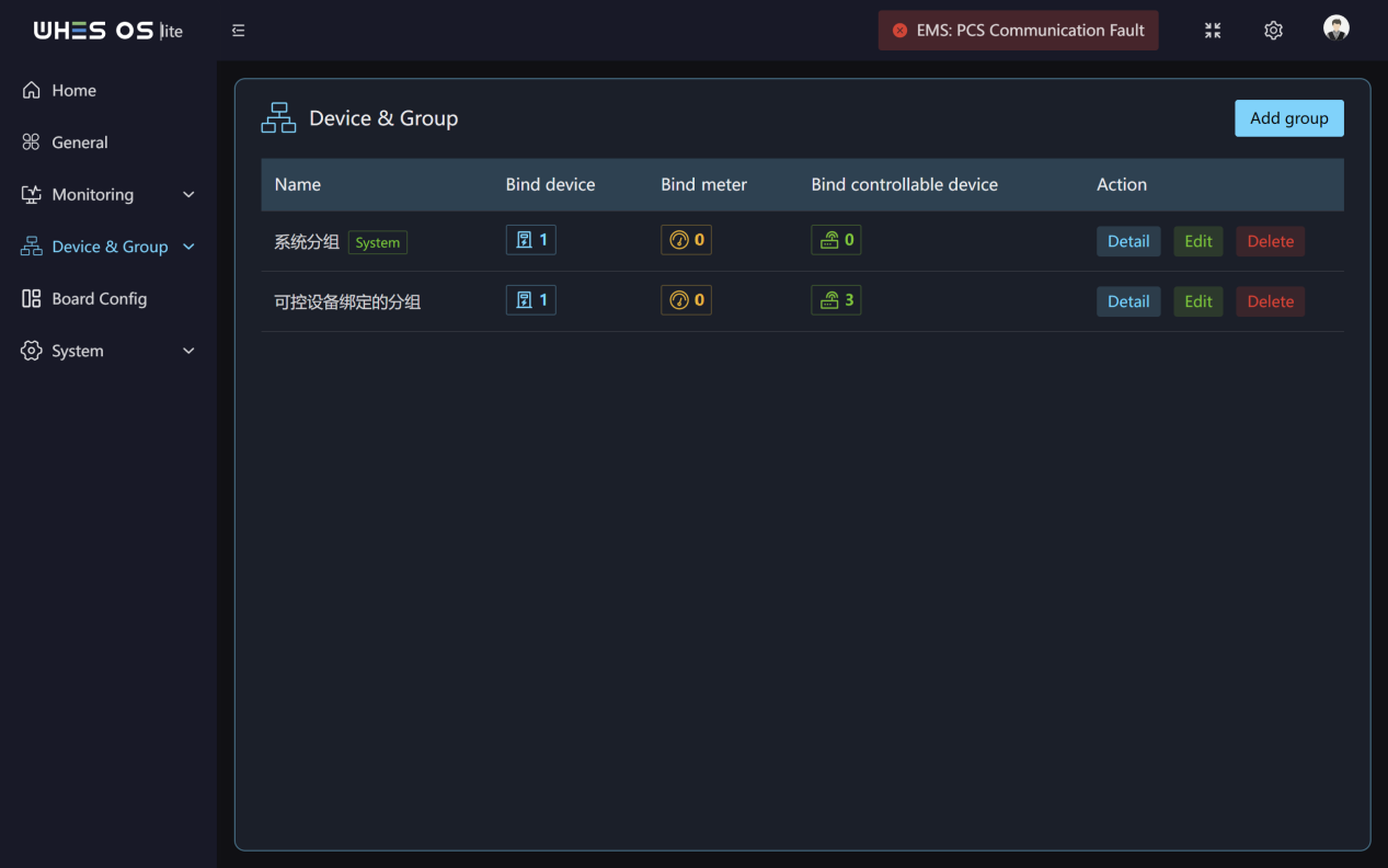
- By clicking “Add group”, you can bind selected devices, meters, and controllable devices to the same group.
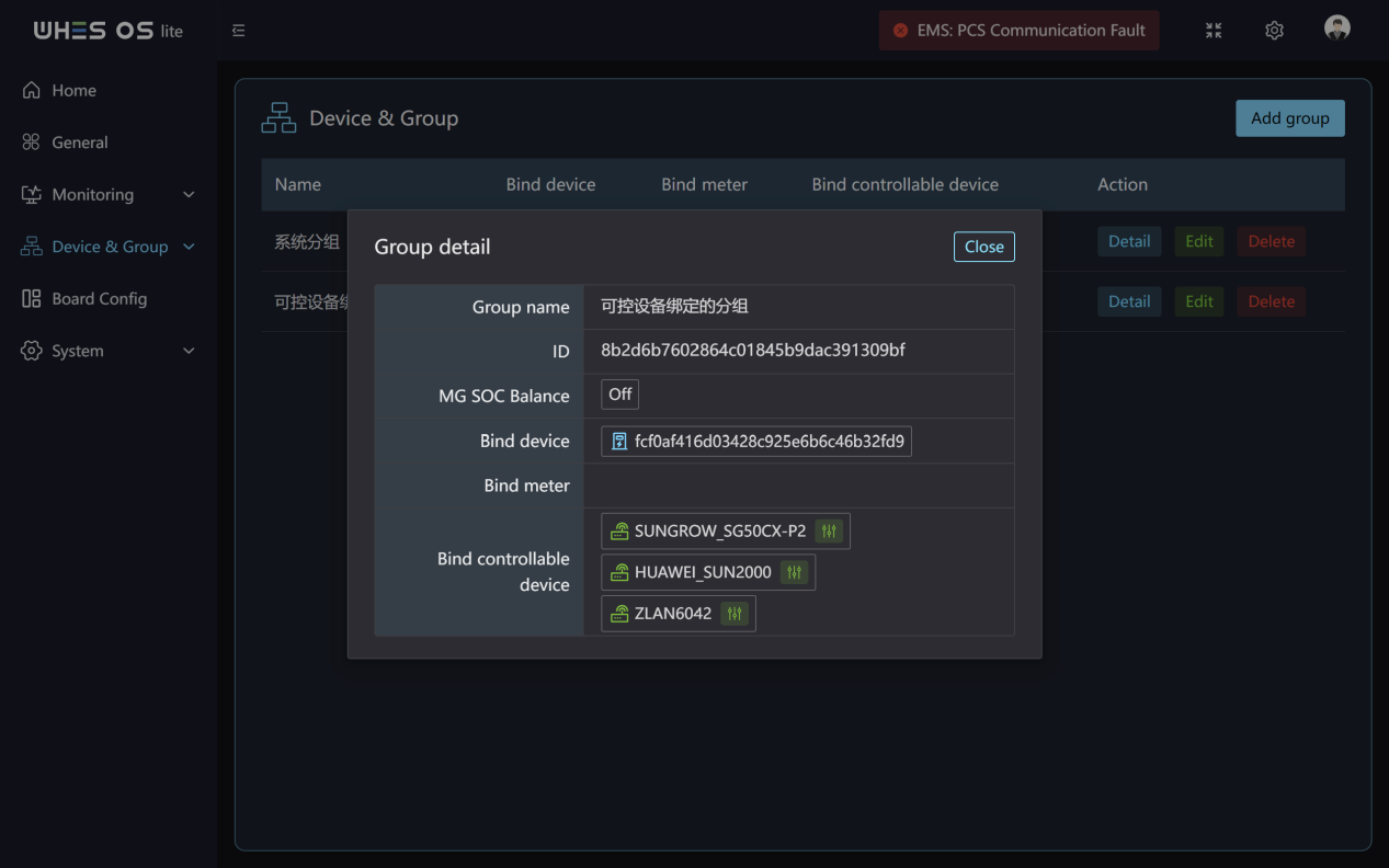
- You can check the group details or edit and delete the group at any time.
- You can configure the mode of the controllable device by hovering the mouse over the bound controllable device, and support adding multiple modes.
Controllable Device
Feature Screen:
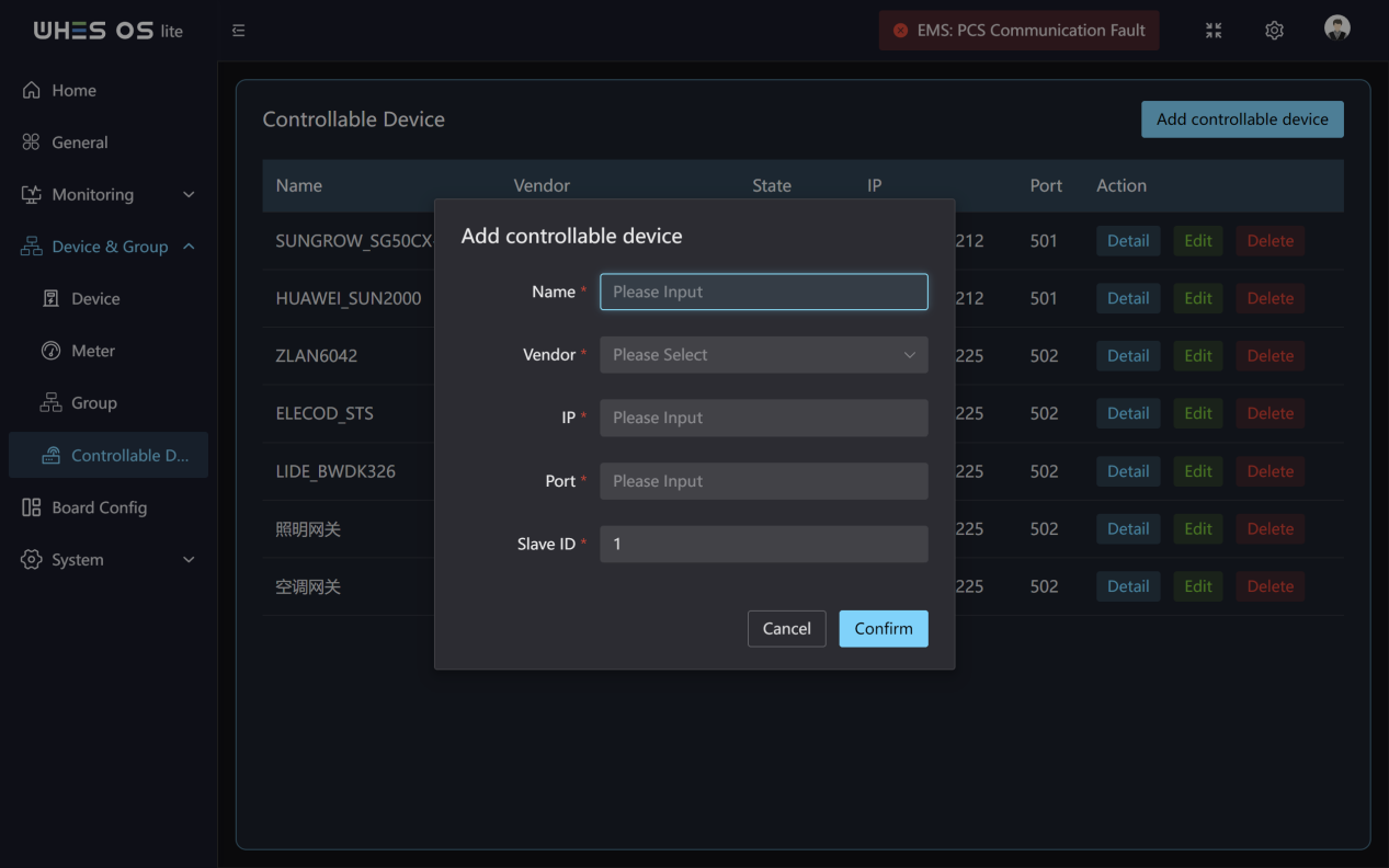
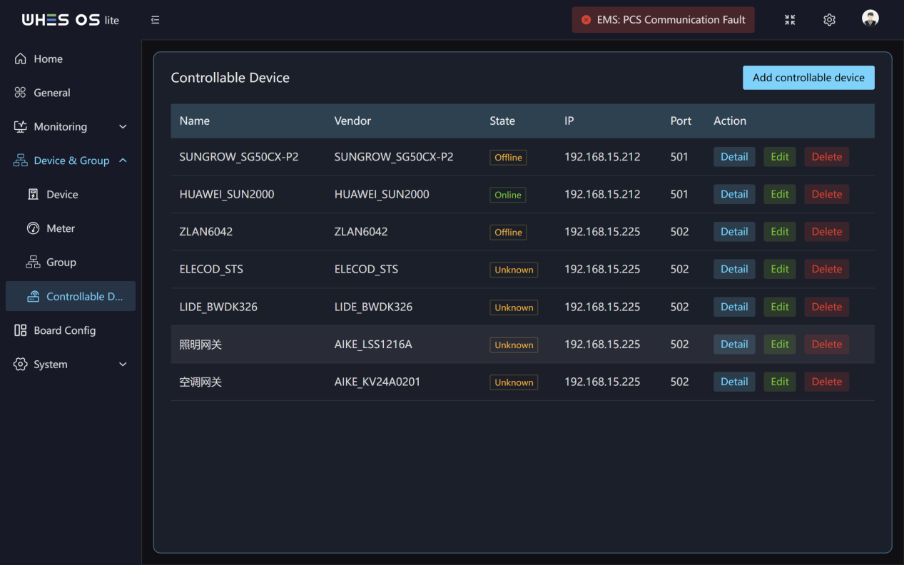
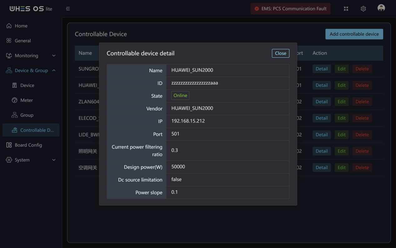
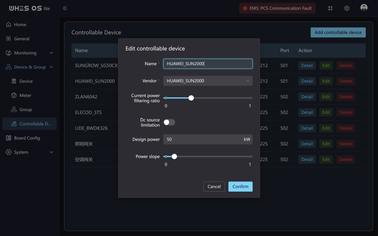
Functions:
- By clicking “Add controllable device”, you can bind selected devices, meters, and controllable devices to the same group.
- You need to enter the name, IP, Port, Vendor and Slave ID of the controllable device.
- You can check the controllable device details or edit and delete the device at any time.
- You can also config the controllable device mode in the group.
Board Config
Feature Screen:
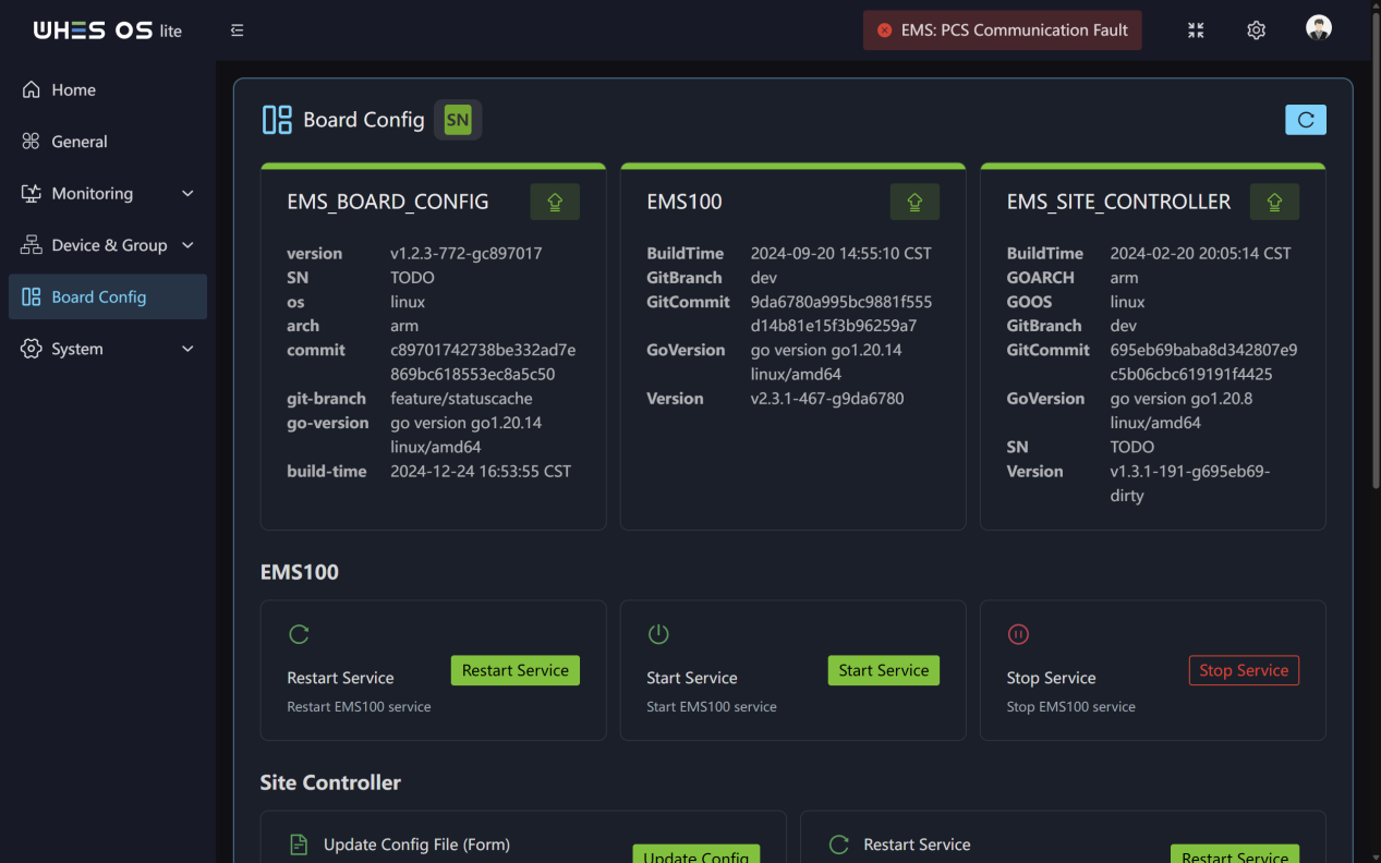
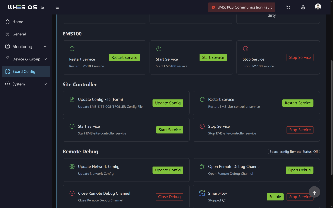
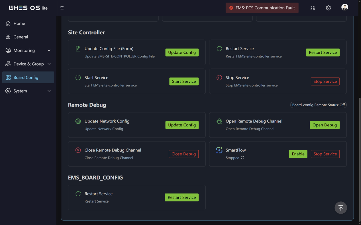
Functions:
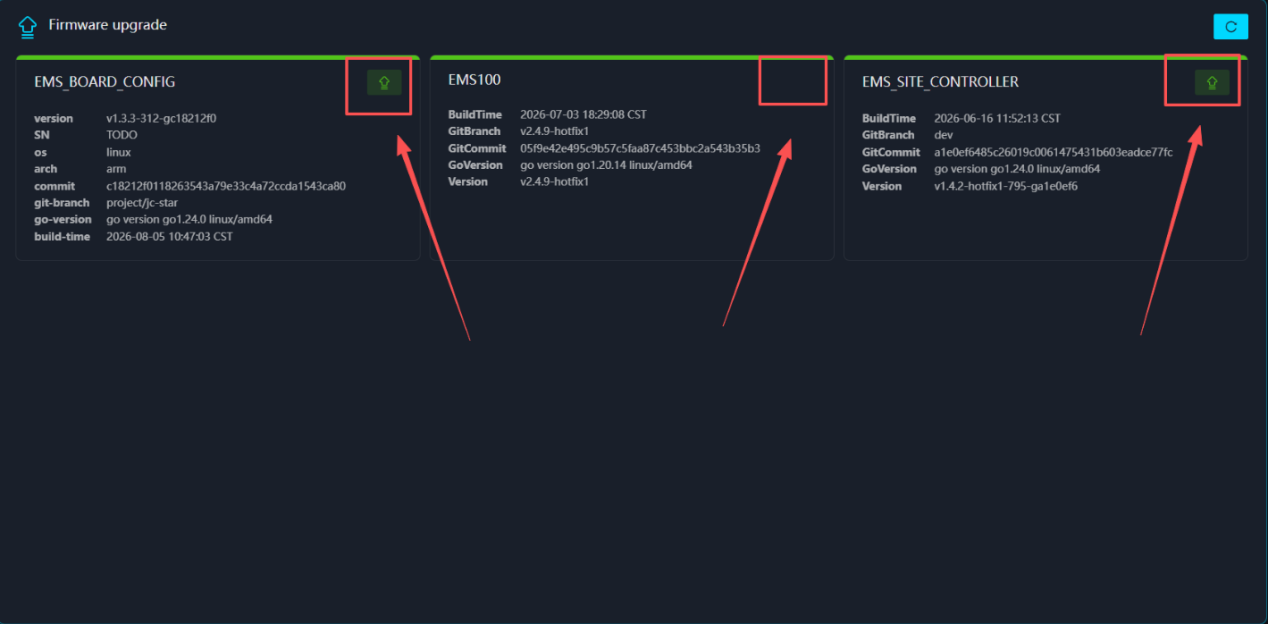
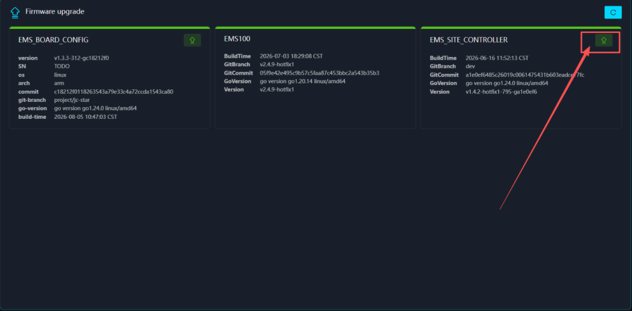
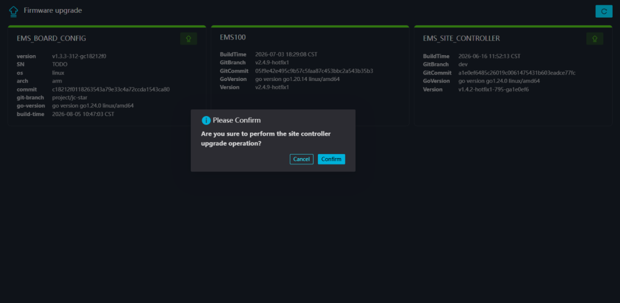
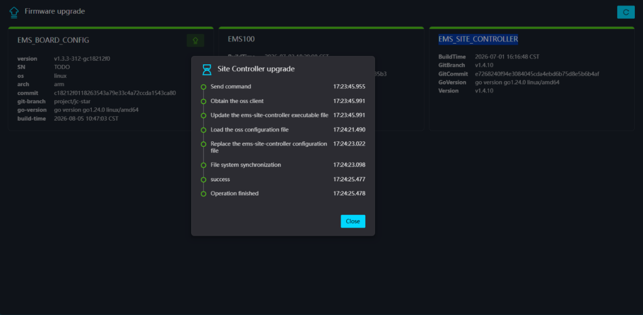
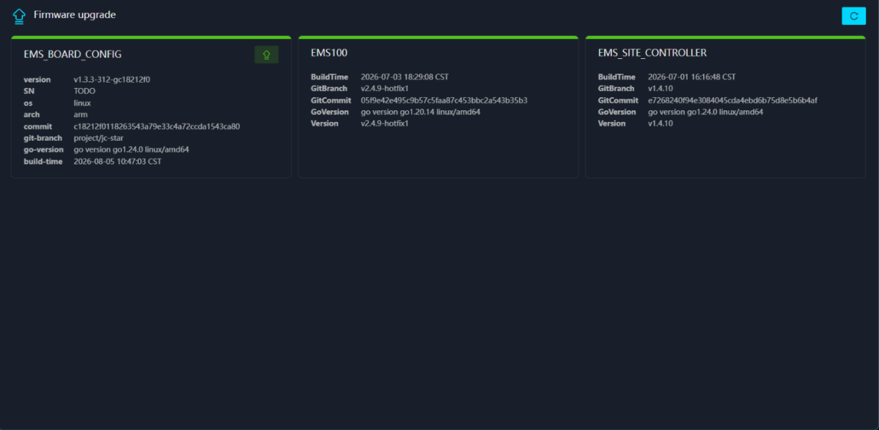
- The upgrade page consists of three “cards,” each representing an online upgradeable component. The “green arrow” in the upper right corner of each card indicates that there is an upgradeable version for that component; the absence of an arrow indicates that no upgrade is required. The “version” field corresponding to each card shows its current version. Click the green arrow next to the corresponding component and confirm to proceed with the upgrade; in this example, we will use the “EMS_SITE_CONTROLLER” component located on the far right. When the upgrade process reaches “Operation finished”, the upgrade is complete: the arrow in the upper right corner of the card disappears, and the version will be updated to the latest version.
Additional Notes:
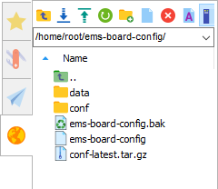
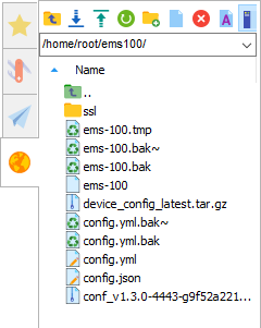
The persistence file directories corresponding to the three modules, from left to right, are:
- /home/root/ems‑board‑config/ems‑board‑config
- /home/root/ems100/ems‑100
- /home/root/ems‑site‑controller/ems‑site‑controller
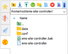
Note: The system will send a firmware update notification. If the user fails to complete the firmware update after receiving the upgrade prompt, any resulting device malfunctions or security risks shall be the sole responsibility of the user.
- You can perform the following controls: restart, start, or stop EMS100; update the configuration file or restart, start, or stop the site controller; and restart EMS_board_CONFIG. As well as You can update the remote debugging network configuration, enable or disable the remote debugging channel, and activate SmartFlow.
System
System Info
Feature Screen:
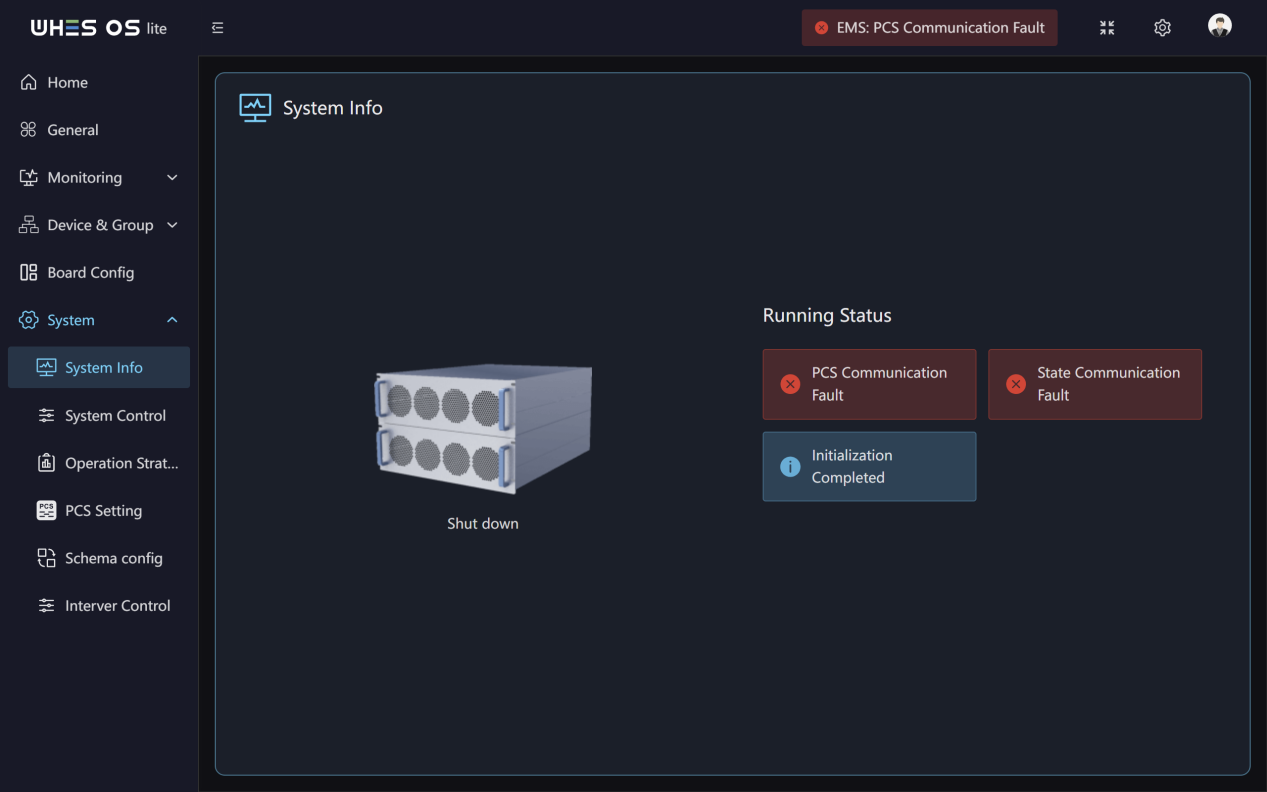
Functions:
This page shows the real‑time status of the system.
System Control
Feature Screen:
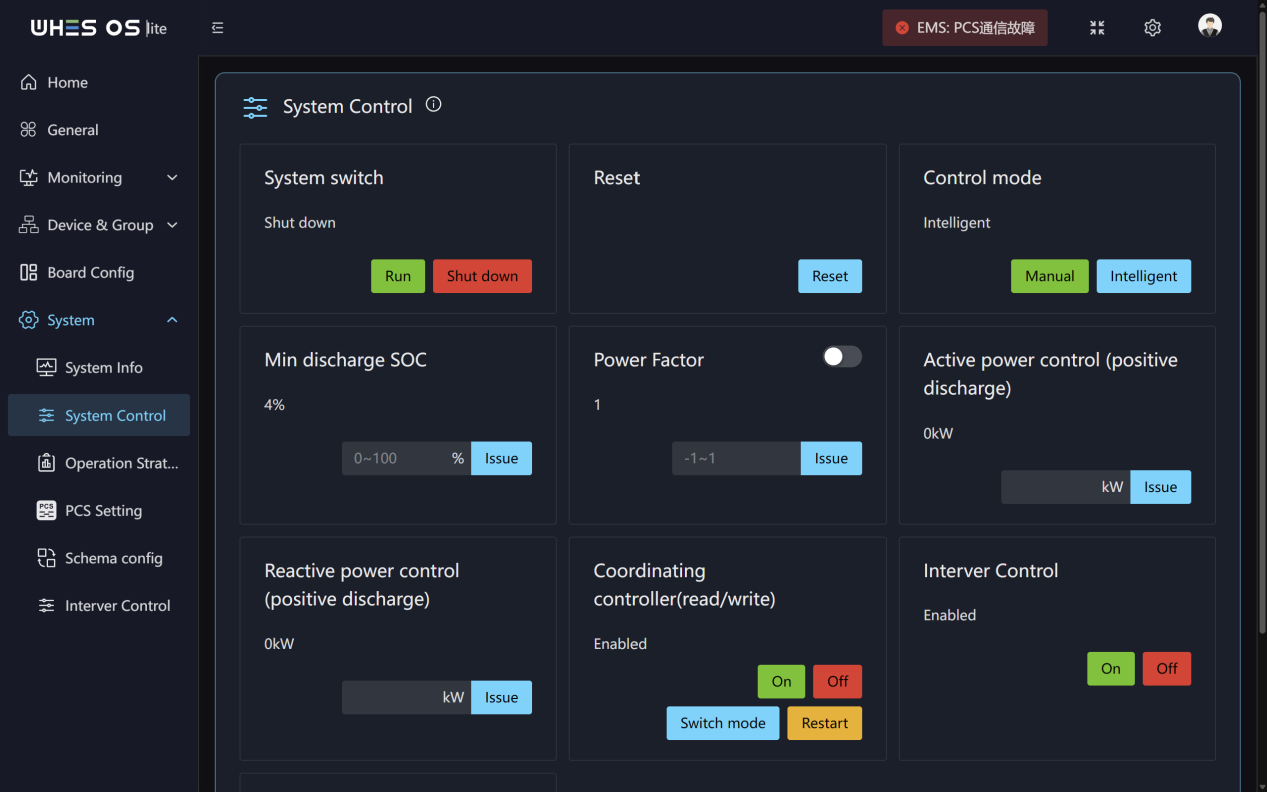
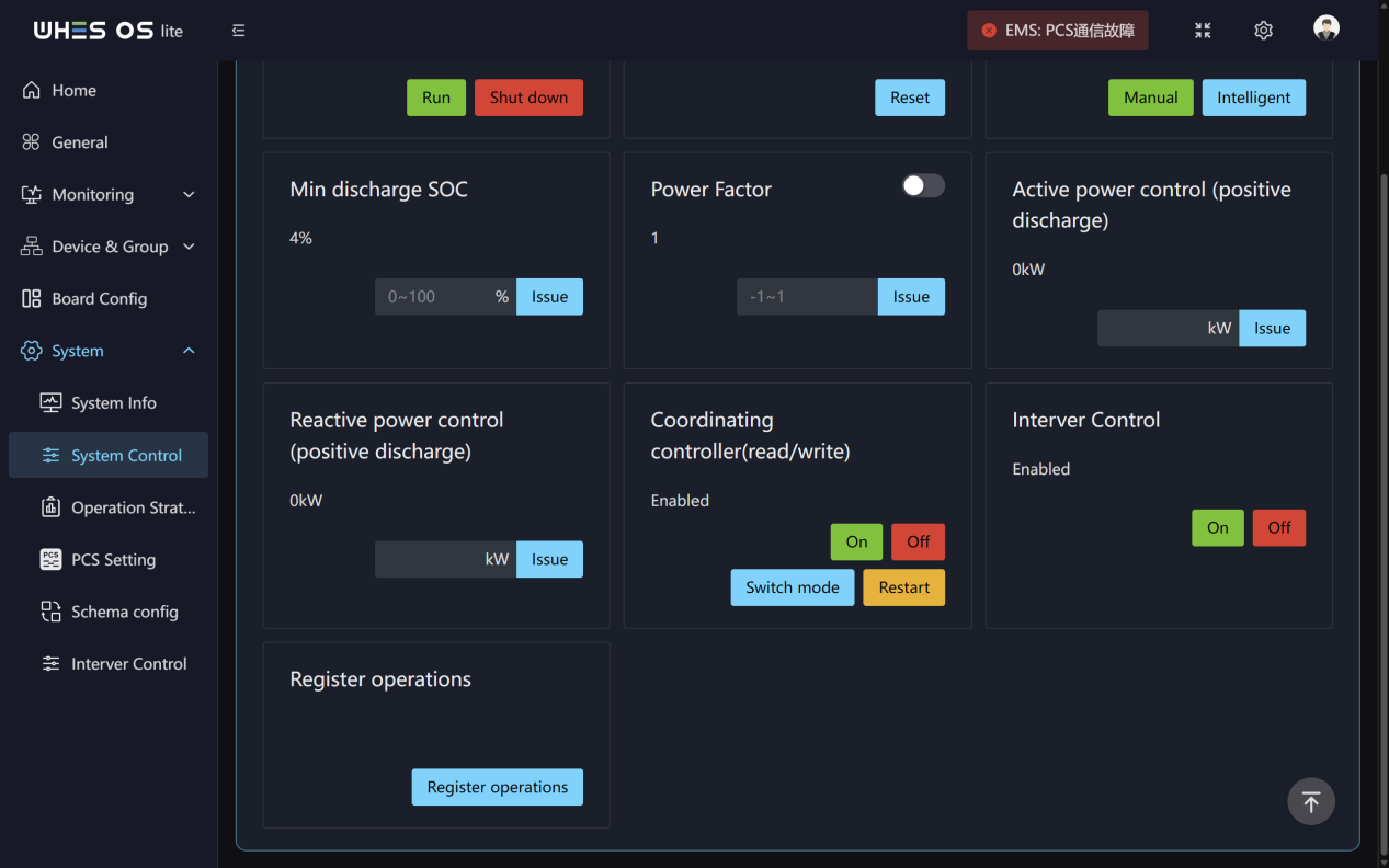
Functions:
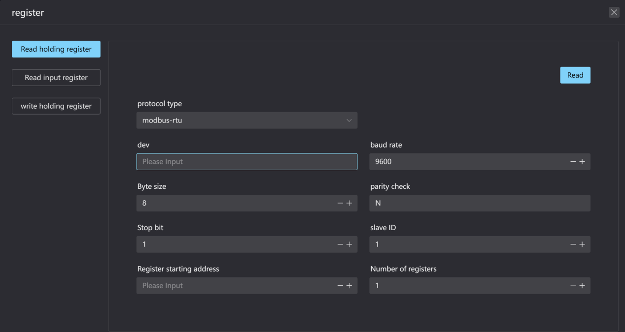
- This page supports performing system controls including system switch, System Reset, On/ Off grid switch, Control mode, Minimum discharge SOC, Power factor, Active power control, Reactive power control, coordinating controller switch, Interver Control.
- As well as you can perform Read holding register, Read input register, and write holding register operations by selecting the protocol type and entering the dev, baud rate, Byte size, parity check, Stop bit, slave ID, Register starting address, and Number of registers.
Operation Strategy
Feature Screen:
Functions:
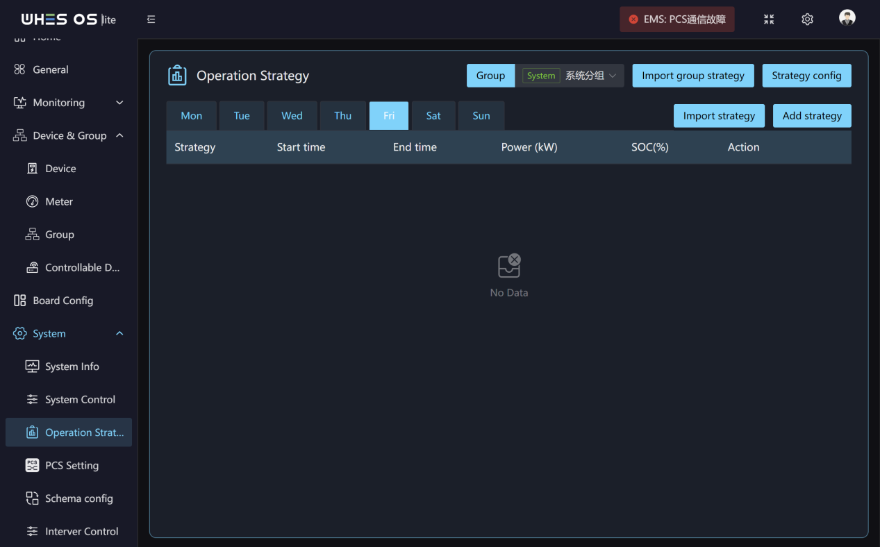
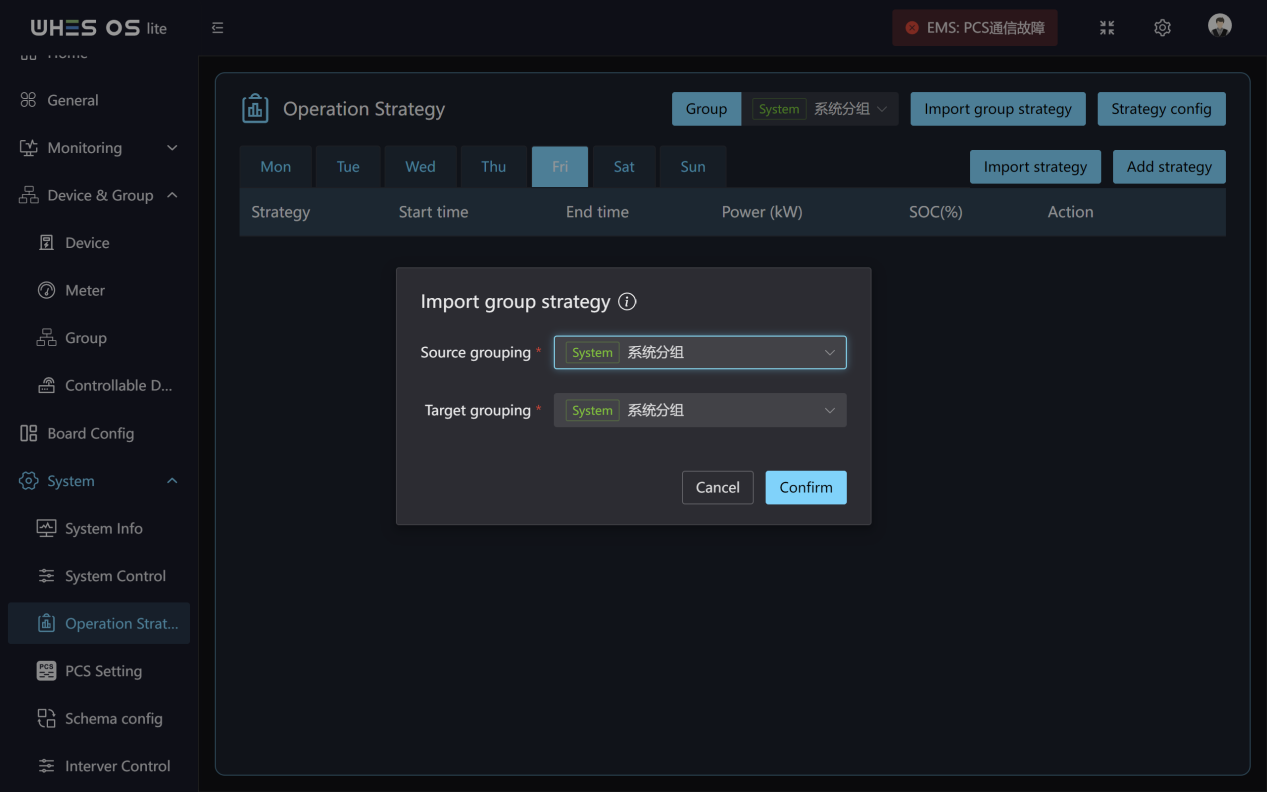
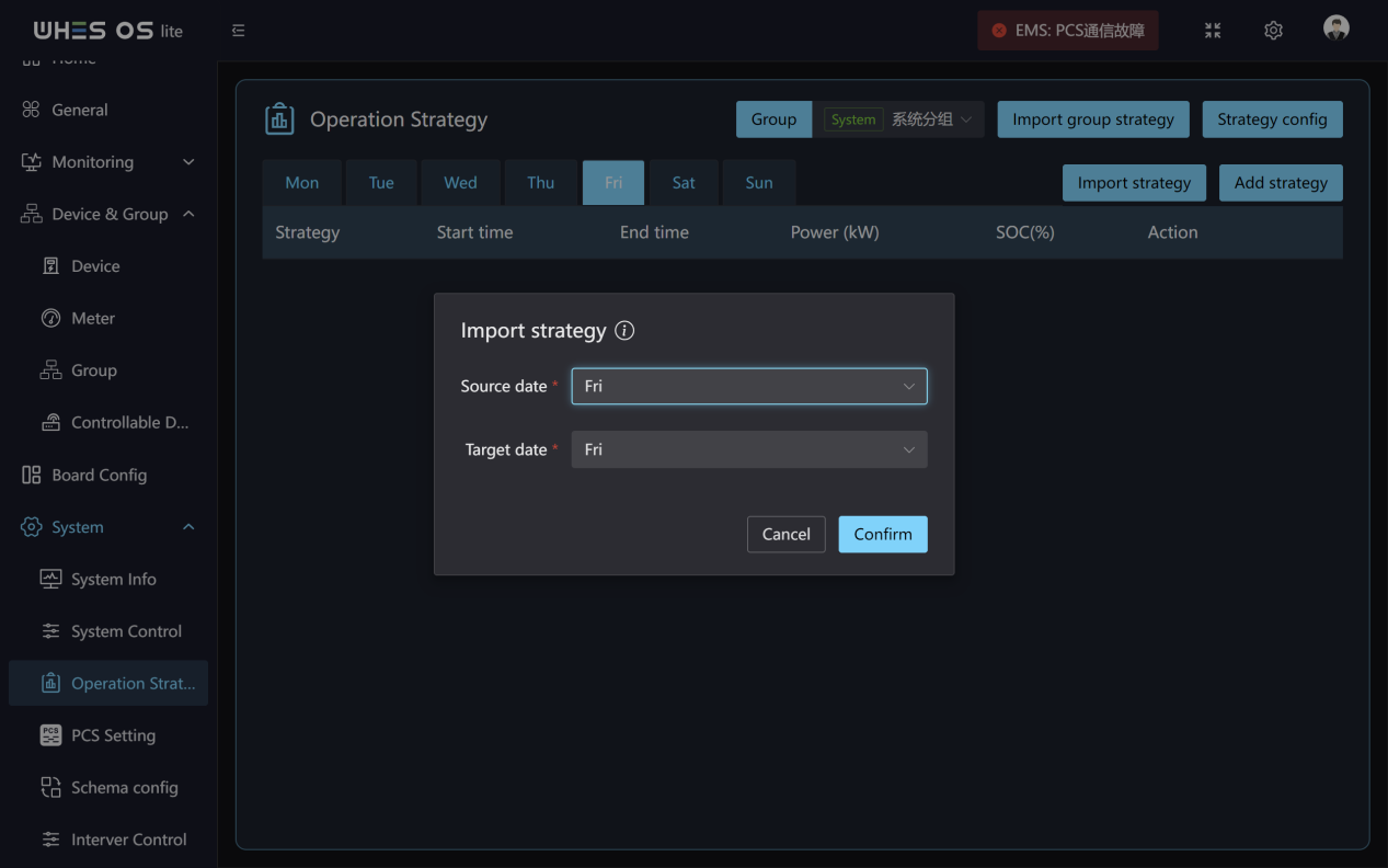
- Operation strategy: This page shows the charge/discharge strategy set for each day of the week, including strategy name, start time, end time, set power, set SOC, edit and delete the strategy.
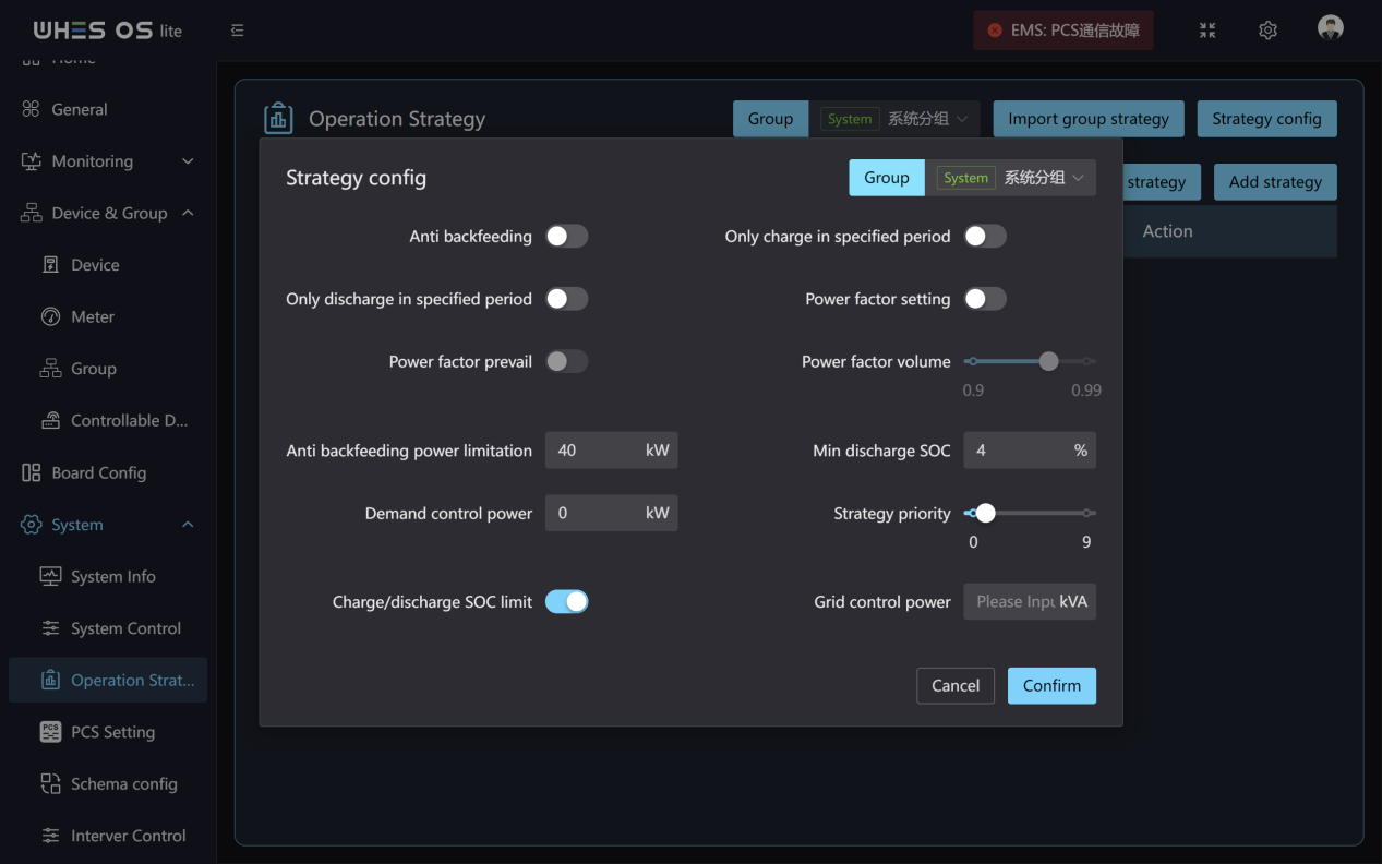
- Strategy config: By clicking the “Strategy configure” button, you can set the strategy for each group.
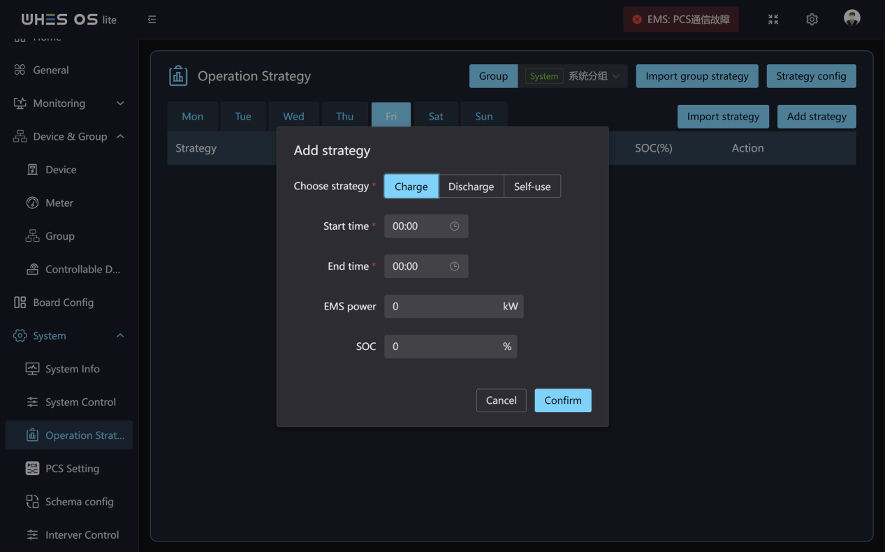
- Add strategy: Click “Add strategy” button, you can choose battery charge/discharge, start/end time, set power, SOC and click confirm to add strategy.
- Import group strategy: Import group strategy allows you to import the strategy from one group to other groups.
- Import strategy: Import strategy allows you to import the strategy from source date to target date.
Pcs Setting
Feature Screen:
Functions:
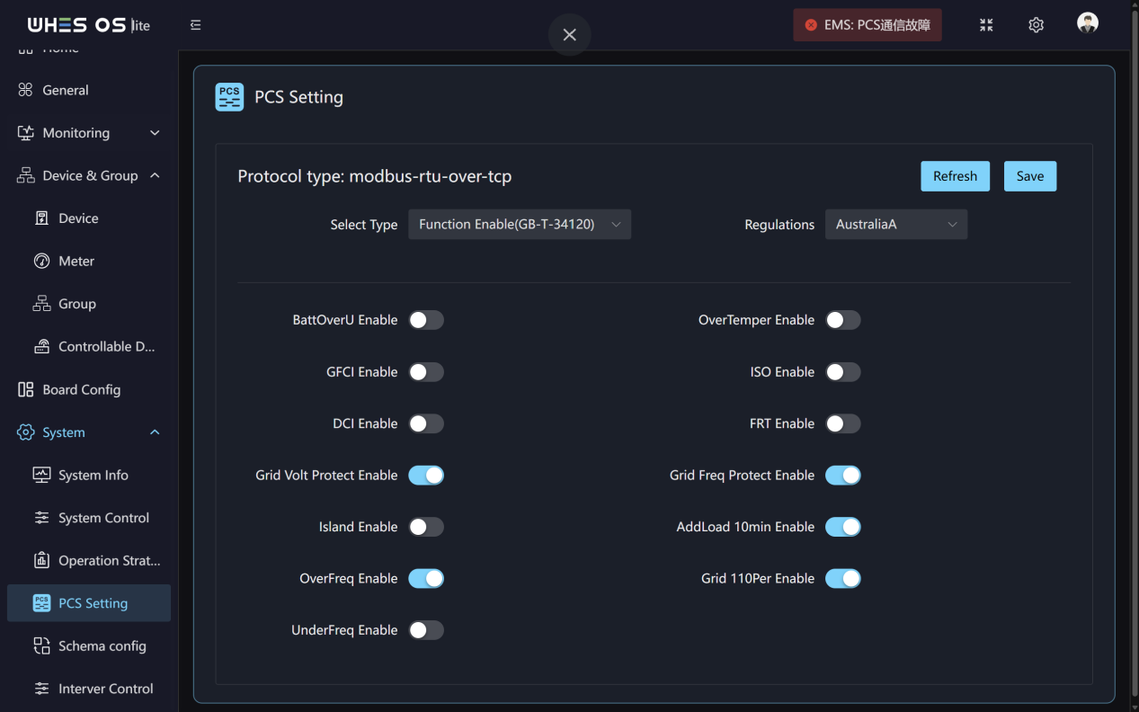
This page allows you to configure the operating parameters and grid compliance switches for the PCS. Select the type and regulations, then make the corresponding settings.
Schema config
Feature Screen:
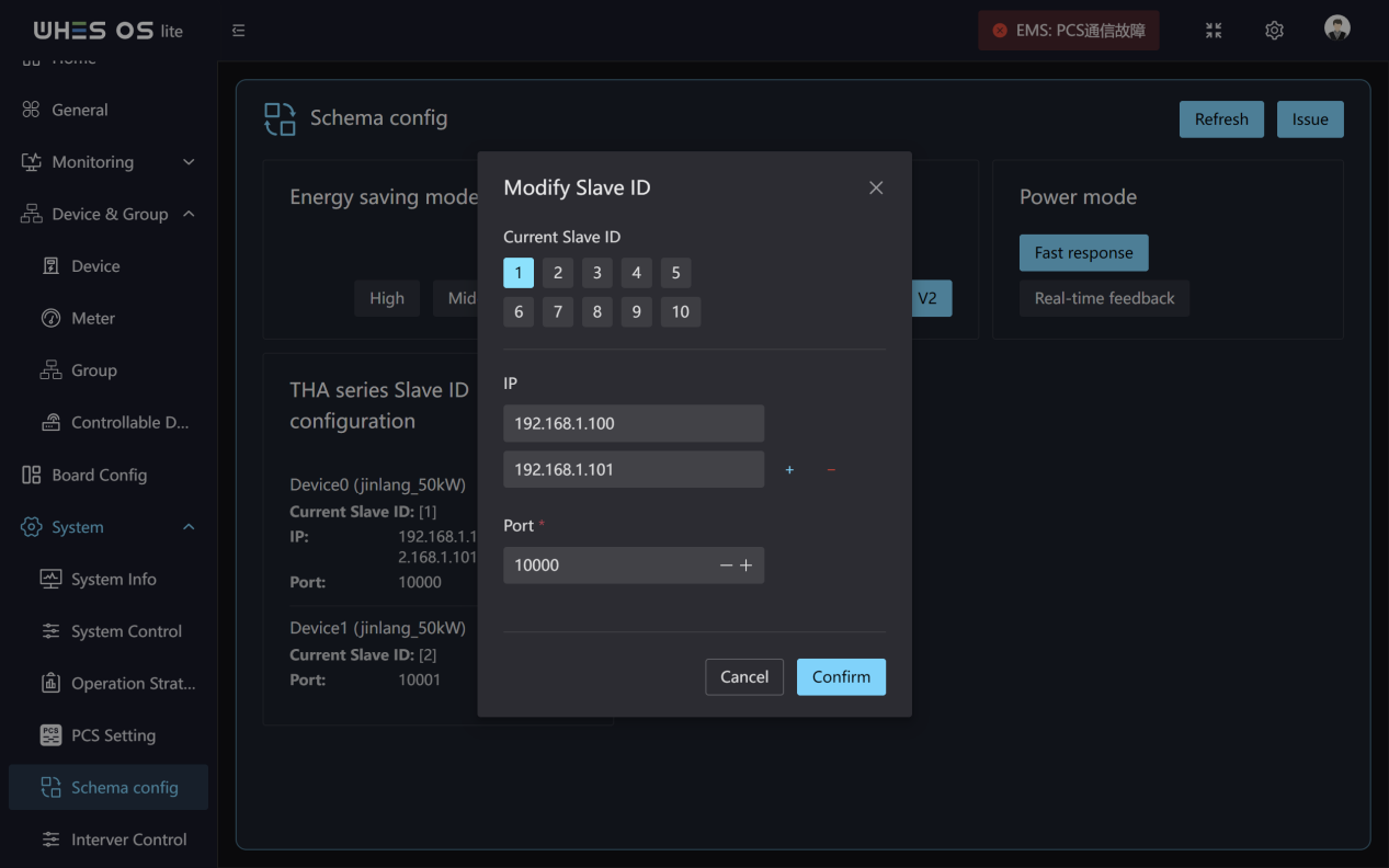
Functions:
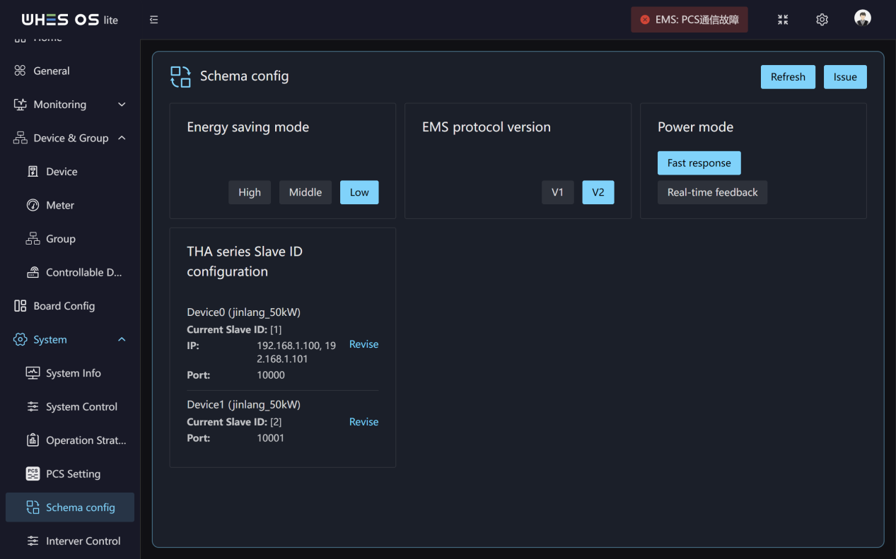
- On this page, you can switch the system’s Energy saving mode level (High/Medium/Low), EMS protocol version (V1/V2), and power mode (Fast Response/Real‑Time Feedback) with one click.
- You can also modify the Current Slave ID, IP and port of THA by clicking “Revise”.
Interver Control
Feature Screen:
Functions:
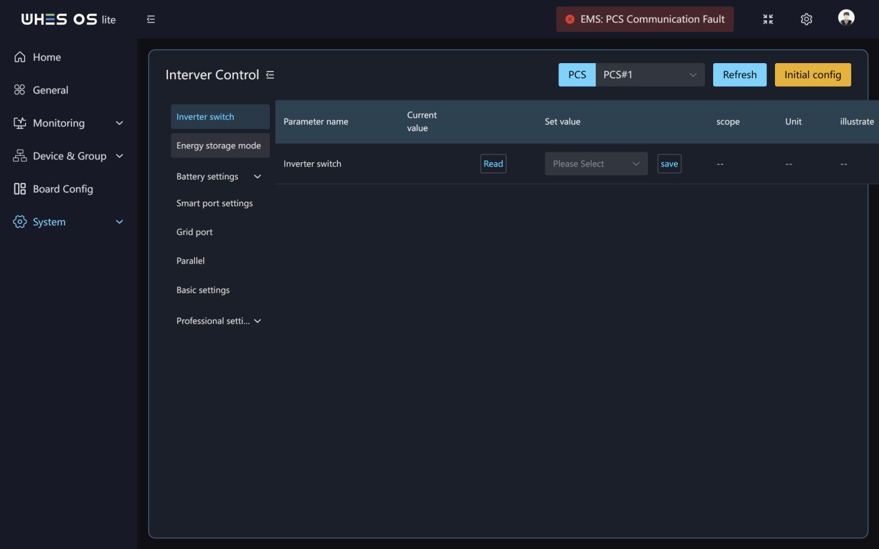
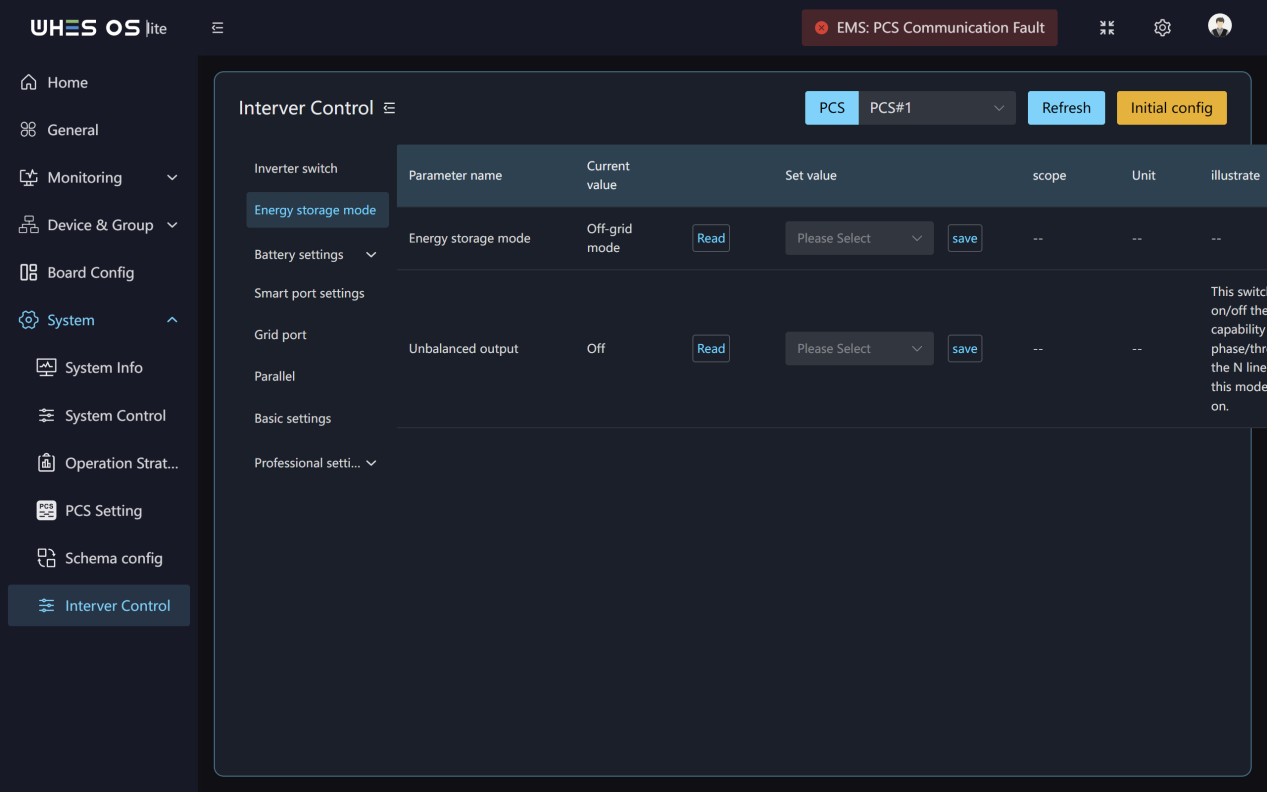
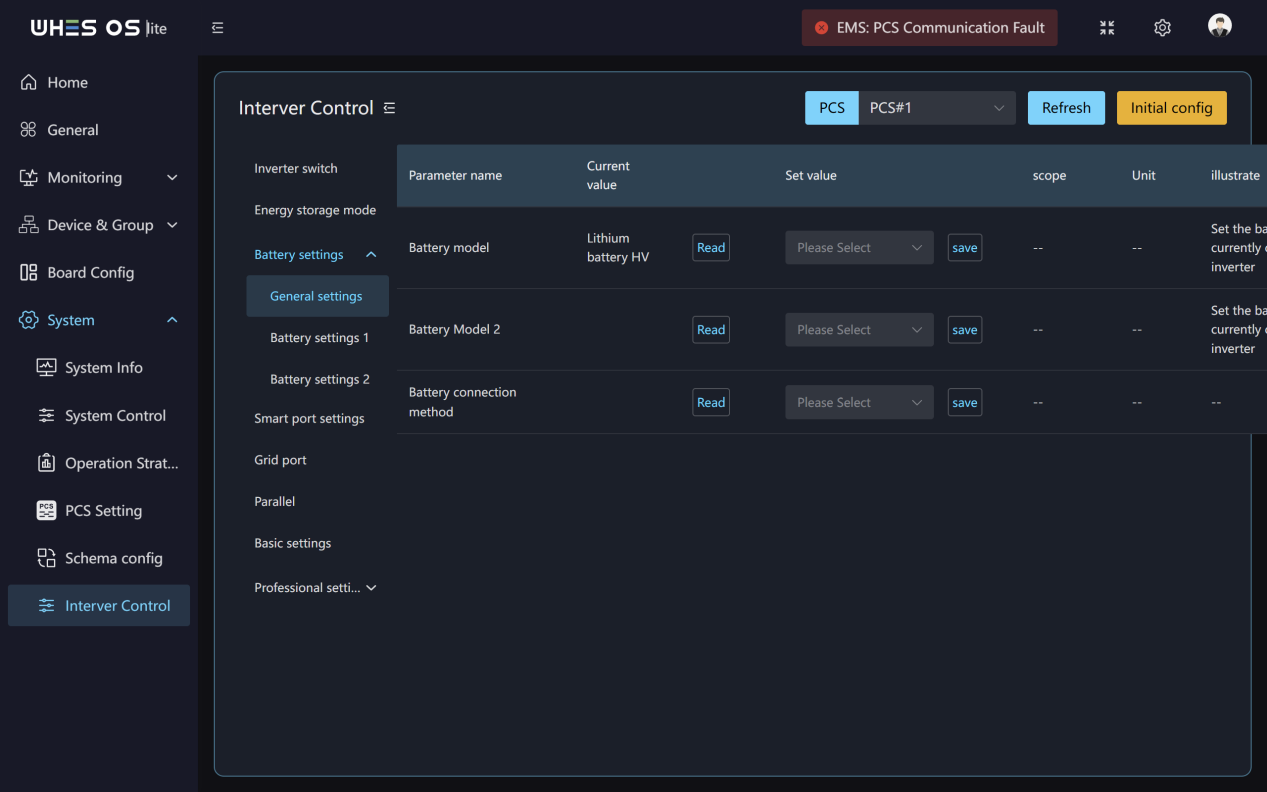
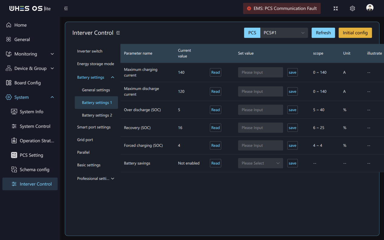
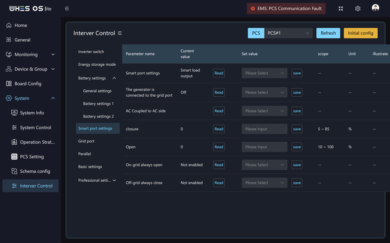
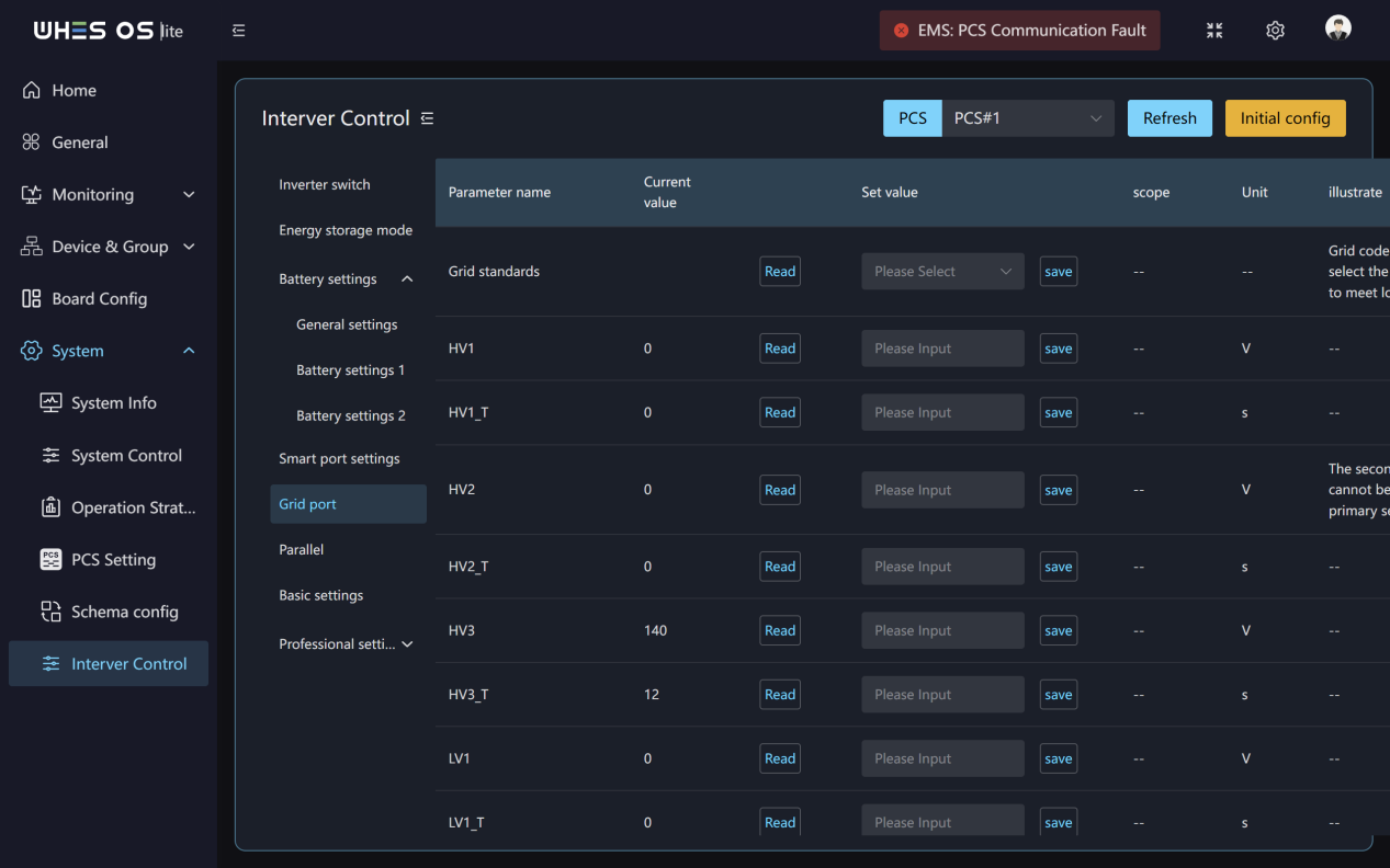
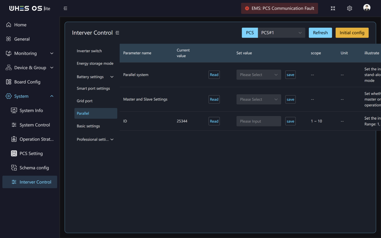
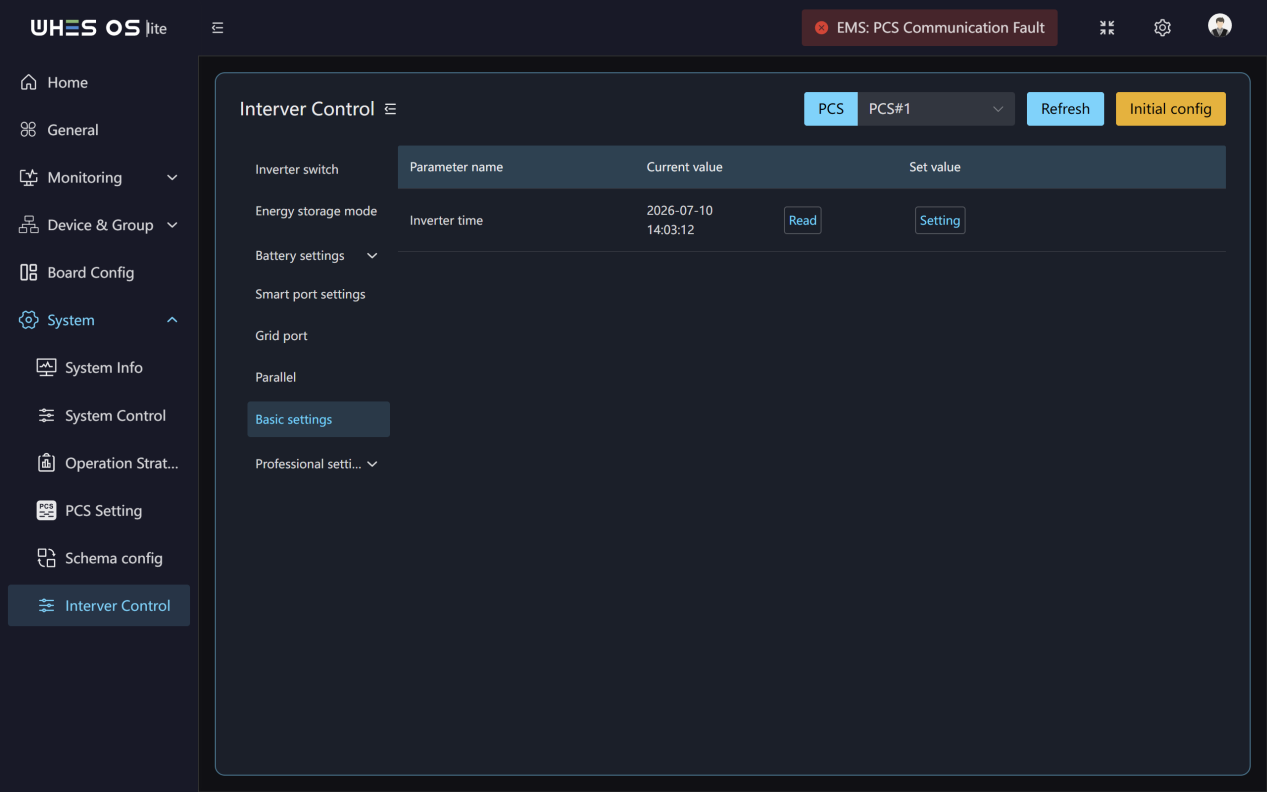
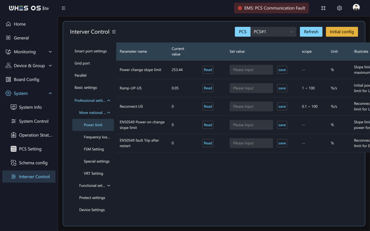
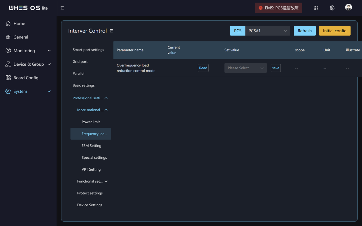
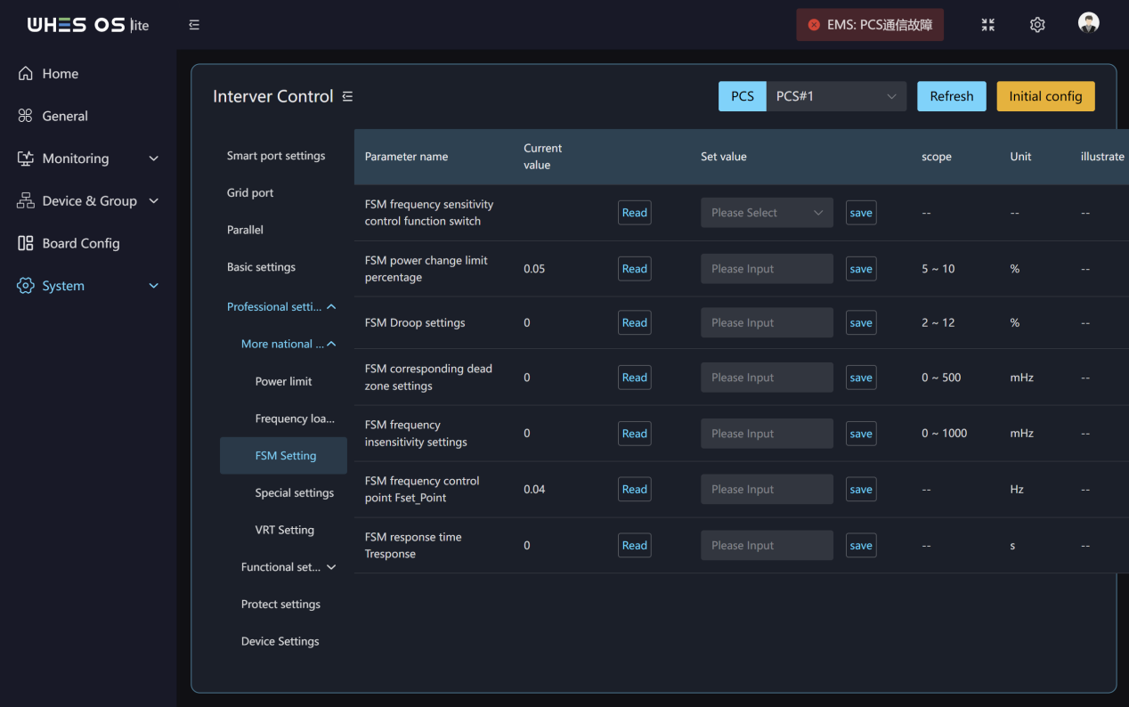
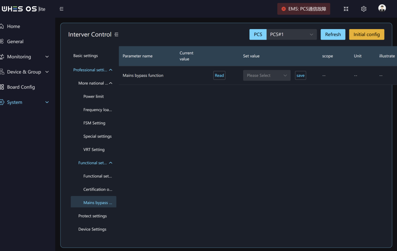
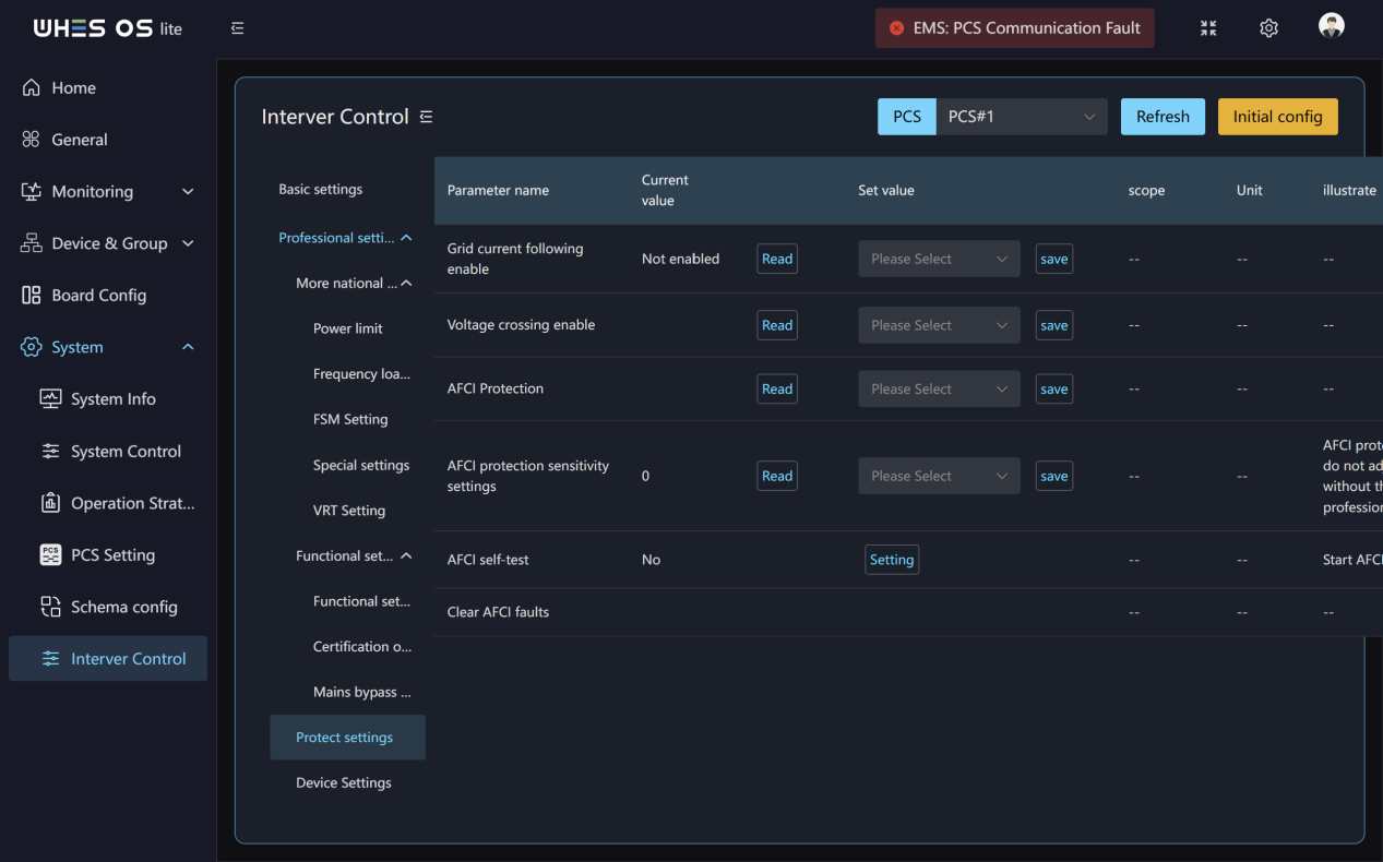
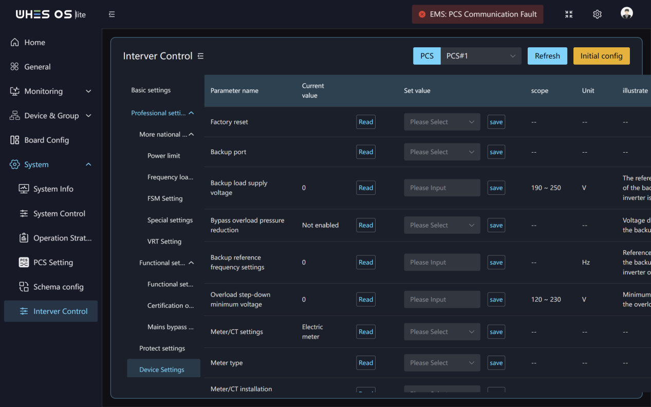
- This page enables detailed parameter reading, writing, and debugging at the Inverter Control. You can select a device and switch between different dimensions in the left menu, independently controlling device parameters using “Read” and “Save”.
- Inverter switch: You can control the inverter’s on/off state.
- Energy storage mode:You can change the energy storage mode and turn it on or off.
- Battery settings: This page enables you to map battery models to connection methods.You can configure the maximum charge/discharge currents for each battery cluster, along with critical SOC safety thresholds for over‑discharge, recovery, and forced charging.
- Smart port settings: You can configure the output logic of the inverter’s smart port, control the generator is connected to the grid port, the AC Coupled to AC side, as well as control its on/off states and on‑grid always open and off‑grid always close.
- Grid port: You can select the grid standard and configure HV/LV/HF/LF along with their corresponding T values, while supporting the setting of voltage, frequency, and delay references for Startup and Recover modes.
- Parallel: On this page, you can set the Parallel system to “Single machine” or “parallel”, set Master and Slave Settings to “From the machine” or “Host”, and configure the ID.
- Basic settings: You can configure Inverter time.
- Professional settings:
9.1 More national standards related:
(1)Power limit: You can set slope limits for power change, Ramp‑UP‑US, Reconnect‑US, EN50549 Power‑on change slope limit, and EN50549 fault Trip after restart.
(2)Frequency load reduction: You can set Overfrequency load reduction control mode.
(3)FSM Setting: You can configure FSM frequency sensitivity control function switch, FSM power change limit percentage, FSM Droop settings, FSM corresponding dead zone settings, FSM frequency insensitivity settings, FSM frequency control point Fset_Point, FSM response time Tresponse.
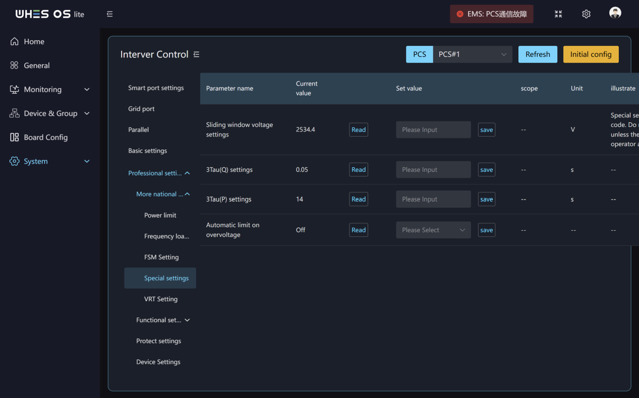
(4)Special settings: You can set Sliding window voltage settings, 3Tau(Q) settings, 3Tau(P) settings, Automatic limit on overvoltage.
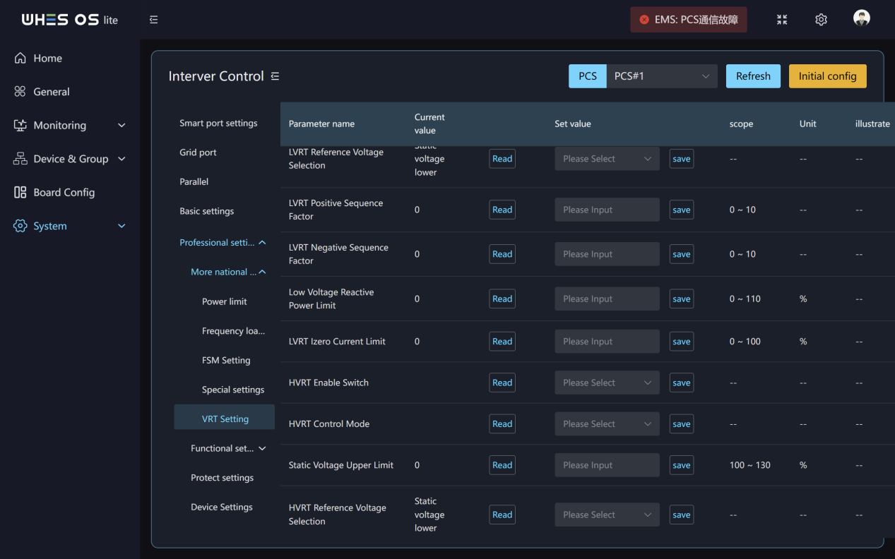
(5)VRT Setting: You can configure the enable switches for LVRT and HVRT, Static Voltage Lower/upper Limit, positive/negative sequence factor, Reference Voltage Selection, Low Voltage Reactive Power Limit, High Voltage Reactive Power Limit, Izero Current Limit, Voltage Sudden Change Switch, Voltage Sudden Change Limit and Q/P Priority Selection.
9.2 Function setting:
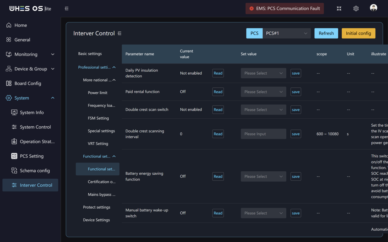
(1)Function setting: You can wake the battery manually or automatically, set the wake‑up voltage and time, and Battery therapy function switch. You can limit the different Logical interface power limit value and enable Battery energy saving function or Low noise mode. You can enable peak‑shaving and configure current output limits. As well as you can enable Daily PV insulation detection and Double crest scan switch.
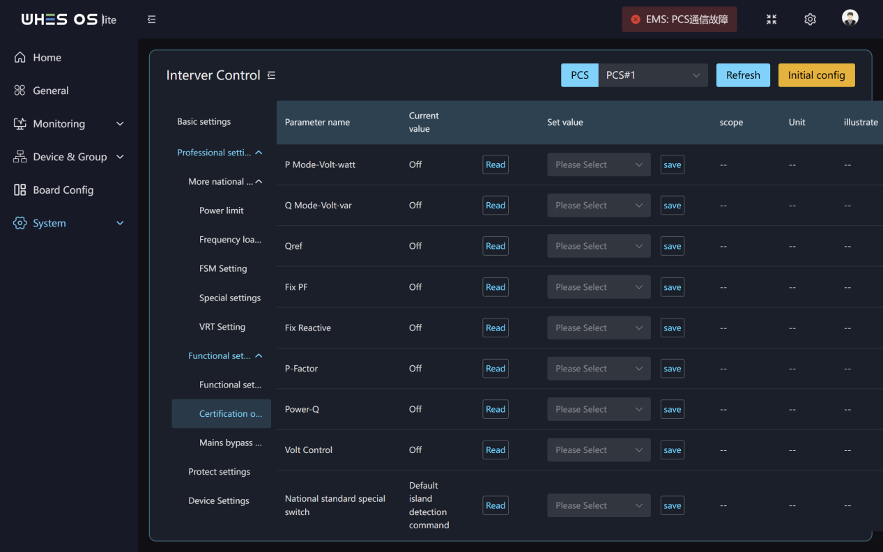
(2)Certification options: You can turn P Mode‑Volt‑watt, Q Mode‑Volt‑var, Qref, Fix PF, Fix Reactive, P‑Factor, Power‑Q, Volt Control on/off and you can set National standard special switch.
(3)Mains bypass function: You can enable or disable Mains bypass function.
9.3 Protect settings: You can enable or disable Grid current following enable, Voltage crossing enable and turn AFCI Protection on/off. You can also set AFCI protection sensitivity settings and AFCI self‑test.
9.4 Device Settings: This page you can configure factory resets, backup ports, backup load supply voltage, backup frequency, and overload pressure/step‑down voltage settings. You can set up the external electric meter and Current Transformer, including the meter type, installation location, CT direction, and CT change ratio. Also you can enable constant voltage MPPT mode and set a fixed MPPT voltage value. Finally, you can directly adjust the inverter’s maximum output power percentage, reactive power, power factor, and restart power profiles.
Equipment Disposal and Resale Data Security Statement
Risk Warning: If data erasure procedures are not performed before a device is scrapped, resold, or transferred to another party for use, the remaining accounts, configurations, or business data on the device may pose a risk of privacy breach.
Safe Disposal and Data Erasure Procedures
- Log in to the system, select the “Reset to Factory Settings” function, and enter the password correctly.
- Confirming the execution of the factory reset will automatically erase all personal information, business data, user‑defined parameters, user passwords, keys, digital signatures, and other data stored on the device.
- Only after all existing data has been completely erased may the equipment be scrapped, resold, or transferred.
Note: Simply performing a deletion operation is not sufficient to completely erase data; you must fully execute the factory reset procedure. After resetting the device to factory settings, proceed with its disposal or resale to mitigate the risk of residual privacy data leakage.